Quotation form
Send an inquiry
Start with the basics. Our team can follow up for missing drawings, standards or packing details.
Submitted details are used only for quotation, technical review and project communication.

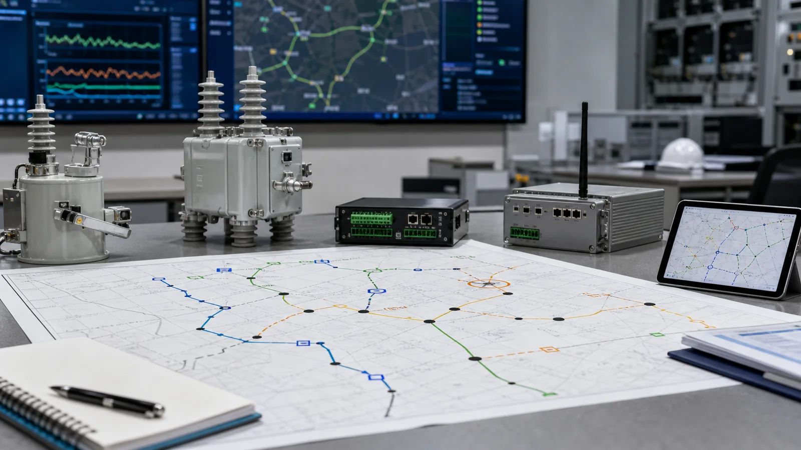
Feeder automation design inputs must freeze the operating objective, topology states, protection and switching boundaries, device duty and interfaces, control-power continuity, communication and data behavior, cybersecurity responsibility, and local or manual fallback before detailed procurement. These inputs constrain one another. An undefined tie state changes protection and command logic; an incomplete point list blocks communication review; an uncalculated energy budget makes control-power selection arbitrary. A single-line diagram plus a protocol name is therefore not a complete design basis. This guide provides a system-level release framework before a project moves into device-role assignment or controller procurement within a smart grid equipment package.
Begin with the operating result the scheme must produce, then describe every feeder state needed to achieve it. A static one-line diagram identifies equipment locations, but not permitted transitions, command authority, protection changes, or degraded behavior.
| Design gate | Required input | Release evidence | Hold condition |
|---|---|---|---|
| Operating objective | Required response in normal, fault, restoration, and degraded conditions | Approved functional description | Objective remains verbal or ambiguous |
| Normal topology | Normally open and closed points, source, feeder, and branch boundaries | Controlled one-line and switching register | Device position or state is unconfirmed |
| Alternate or tie state | Permitted transfer state, loading basis, protection intent, and close authority | State diagram and approved sequence | Tie is shown without transition rules |
| Fault response | Isolation boundary, restoration intent, and sequence owner | Logic narrative or sequence specification | Actions are assumed from device locations |
| Maintenance state | Isolation, bypass, automation inhibit, and return-to-service state | Maintenance-state design note | Maintenance would defeat adjacent automation |
| Protection ownership | Zone owner and handoff at each switching point | Coordination basis or responsibility matrix | Boundaries are implied, not assigned |
| Fallback state | Behavior after loss of communication, control power, or automation | Defined state for each point | Loss-of-service behavior is absent |
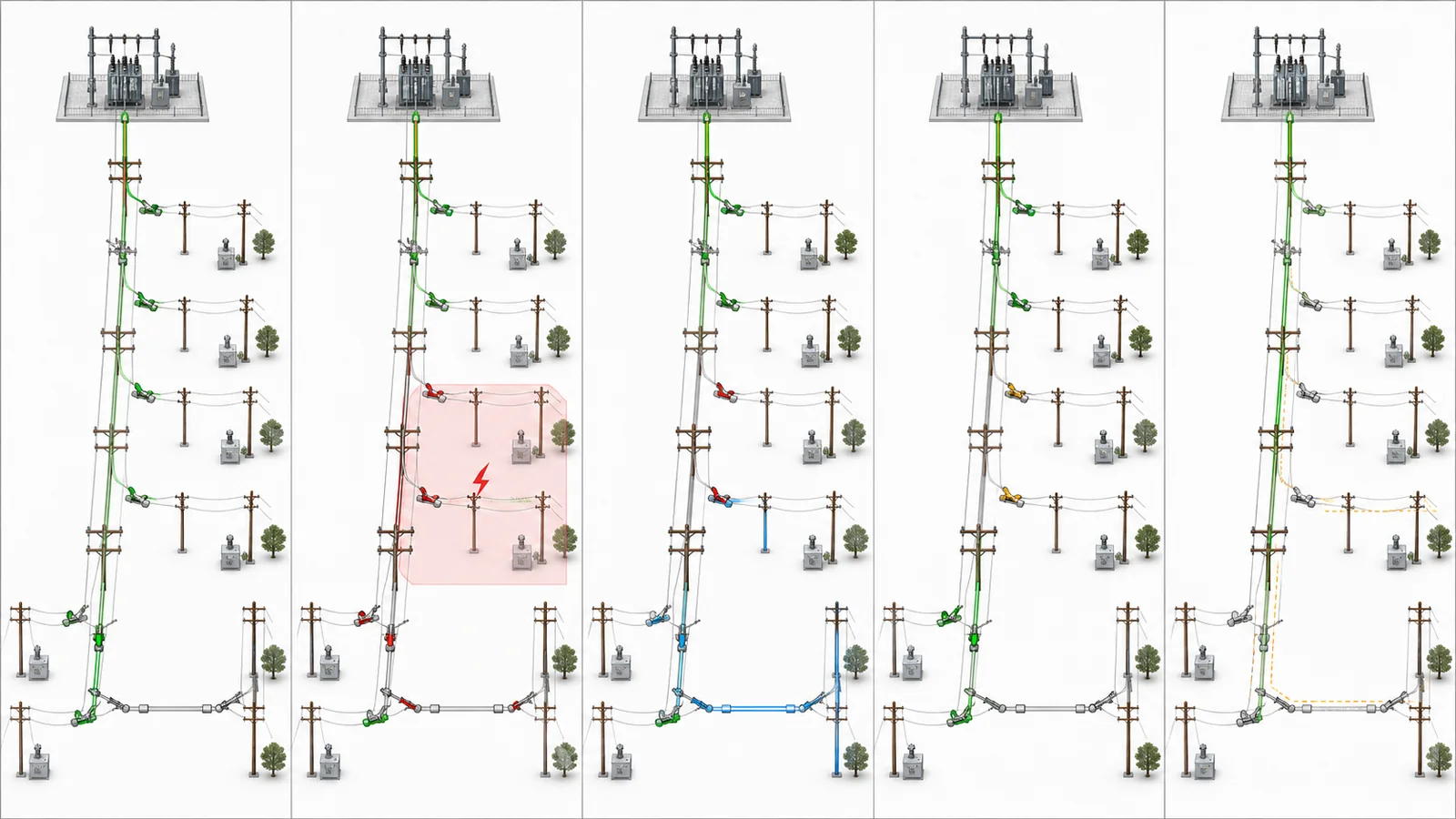
Each state also needs an owner. The design must distinguish autonomous actions, operator-confirmed commands, local-only actions, and prohibited transitions. This prevents a drawing symbol from being mistaken for an approved operating sequence. It also exposes conflicts early: a proposed point may be correctly located yet lack the command, sensing, interlock, or energy interface needed for its intended sequence.
Translate each feeder position into system duties before naming a device family. The purpose is to define what the position must do and what evidence will prove that a proposed package can do it.
| Feeder position | Duty to define | Interface inputs | Evidence before release |
|---|---|---|---|
| Source exit | Protection-zone origin, fault interruption, and reclosing intent where applicable | Load and fault basis, sensing, trip/close, status, sequence | Fault study and coordination basis |
| Mid-feeder point | Isolation, sectionalizing, and transfer support | Switching duty, withstand duty, sensing, commands, status, interlocks | Approved sequence and zone assignment |
| Lateral or branch | Branch isolation without an unintended trunk operation | Load/fault duty, local operation, sensing, status | Branch protection and operating basis |
| Normally open tie | Controlled transfer and safe close permission | Making duty, voltage-check logic where required, close authority, state feedback | Transfer and protection-change specification |
| Customer boundary | Demarcation, protection handoff, and monitoring | Boundary duty, trip interface, status, responsibility | Boundary study and ownership record |
| Maintenance point | Safe isolation without defeating adjacent functions | Visible isolation, bypass, grounding interface where required, interlocks | Isolation and bypass design |
For every position, record the voltage and continuous-current basis; fault-making, breaking, or withstand duty as applicable; load switching or isolation requirement; operating sequence; sensing; command interface; auxiliary status; local/manual operation; interlocks; maintenance isolation; environment; mounting; and line or cable connection. An automatic vacuum circuit recloser illustrates why the switching body and controller layer must be reviewed separately. A user boundary switch adds a demarcation and coordination boundary that cannot be inferred from its location alone. For basic terminology, see the recloser protection and automation primer.
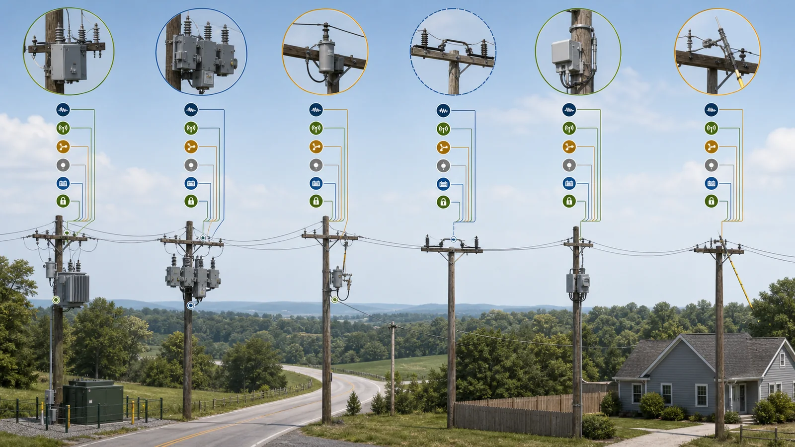
This article does not assign recloser, sectionalizer, load break switch, or boundary-switch roles. That choice follows only after the position duties and interfaces are approved.
Automation can lose function even when the primary switching rating is correct. Each location needs a control-power source, verified operating range, load and energy budget, continuity objective, supervision method, and defined behavior when available energy falls.
| Load or state | Required function | Input to calculate | Sequence basis | Evidence owner |
|---|---|---|---|---|
| Normal standing load | Monitoring, control readiness, and communication | All continuous loads | Continuous operating state | System designer |
| Primary supply lost | Required monitoring and command availability | Storage and remaining loads | Project-defined fallback period | Project owner |
| Open or trip command | Execute the required operation | Coil, actuator, and interface demand | Approved fault or isolation sequence | Device-package supplier |
| Close or restore command | Close and recharge where applicable | Mechanism and accessory demand | Approved restoration sequence | Device-package supplier |
| Communication | Maintain link and process events | Radio, modem, gateway, or network load | Normal and degraded states | Communication designer |
| Environmental accessories | Heating or other required enclosure loads | Accessory and environment data | Site-specific duty cycle | Enclosure designer |
Calculate standing load, peak demand, command energy, recharge behavior, and any ride-through or autonomy requirement from the selected architecture and sequence. Do not start with a universal battery size or autonomy duration. Define low-energy alarm, operations that become prohibited, the safe fallback state, recovery responsibility, and storage-element maintenance access. The design is releasable only when the budget and the required sequence agree.
A protocol name identifies only part of the interface. The design package must define functions, ownership, points, states, timing, access, and failure behavior.
| Input | What must be frozen | Release evidence |
|---|---|---|
| System owner and path | Master owner, medium, route, segment ownership, and maintenance boundary | Labeled communication architecture |
| Interface basis | Protocol, version/profile, conformance basis, and gateway responsibility | Controlled interface specification |
| Point list | Commands, indications, measurements, alarms, units, quality states, and validity rules | Reviewed point list |
| Command authority | Automatic, operator-confirmed, local-only, and blocked commands | Approved command matrix |
| Events and time | Event priority, storage, retrieval, time source, and project accuracy class | Event and time specification |
| Performance class | Project-defined availability and latency needs by function | Functional performance requirement |
| Cybersecurity ownership | Access approval, authentication, credentials, keys/certificates, logging, and updates | Responsibility and access matrix |
| Loss of service | Behavior after link, master, time source, or remote-access loss | Per-state fallback specification |
IEC 61850-5:2013+AMD1:2022 addresses communication requirements for functions and device models in power utility automation, including communication beyond the substation boundary. That scope supports defining functional requirements before selecting an interface. It does not define feeder topology, switching ratings, control-power autonomy, or the project’s cybersecurity policy. Interoperability still needs an agreed profile, data model or point mapping, conformance basis, ownership, and project-specific testing.
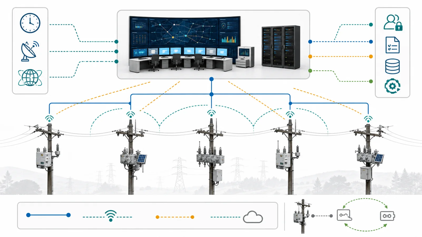
The same discipline applies whether a project uses an IEC-based interface or another protocol. Communication loss must not create an undefined switching state, and remote maintenance access must not be treated as an informal commissioning convenience.
An electrically suitable device can still fail the automation fit. Review all interfaces together, because a change in sensing, control power, state feedback, or communications can alter the package boundary.
| Interface | System requirement | Required package evidence | Typical hold reason |
|---|---|---|---|
| Primary duty | Applicable load, making, breaking, and withstand duties | Ratings and applicable test documentation | Duty or operating sequence is unverified |
| Sensing | Quantity, location, class, output, and burden basis | Sensor and wiring data | Output is absent or incompatible |
| Commands | Signal type, energy, permissives, and fail state | Control-interface schedule | Controller output and actuator input do not match |
| Position/status | State definitions, contacts, quality, and local indication | Auxiliary-contact and state schedule | SCADA state is ambiguous |
| Control power | Range, standing/peak demand, continuity, and supervision | Verified load data | Budget omits a mechanism or accessory |
| Communication/time | Interface profile, points, events, time behavior | Conformance and configuration evidence | Protocol name exists but mapping does not |
| Local/manual operation | Local authority, indication, inhibit, and recovery | Operating and interlock description | Remote loss leaves no defined fallback |
| Installation/maintenance | Environment, mounting, connection, isolation, and bypass | Drawings and maintenance boundary | Physical or isolation interface is unresolved |
A mismatch in one row is a release hold, not a note for commissioning to solve. The review should also name who owns each interface through design, factory configuration, site integration, and service. This keeps missing data from being transferred silently between the utility, EPC, communication provider, controller supplier, and switching-device supplier.
Release detailed engineering and procurement only when one revision-controlled package contains:
Treat this approval-data checklist as the technical release data pack, not as a narrative summary. Trace the applicable rated voltage, rated current, switching and trip-coil interfaces to manufacturer data; trace operating states and acceptance duties to the project specification; and trace the fault basis to the approved short-circuit study. Drawings, interface schedules, calculations, and any applicable test record must identify the same equipment revision and duty. A document title alone is not release evidence.
Representative engineering review, not a XIYA customer project. A radial feeder with a normally open tie and planned remote sectionalizing has a one-line drawing and proposed device locations. Review shows that normal and emergency states are not fully defined, protection-zone ownership is open, the control-power continuity basis is missing, communication ownership is unassigned, the point list lacks quality states, the time basis is absent, and manual fallback is undocumented. The correct decision is a design hold. Each gap receives an evidence owner and release criterion; device-role assignment and controller procurement wait until the inputs agree. This example contains no claimed project rating, customer result, field measurement, or commissioning outcome.
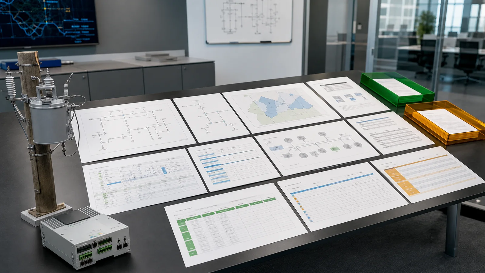
To start an interface-fit review, send XIYA POWER the one-line and topology states, fault/protection basis, switching-duty register, control-power worksheet, communication architecture, point list, and installation conditions. The review identifies complete and open interfaces; it does not promise suitability, compliance, or interoperability before the evidence is checked.
The minimum set is an approved operating objective, topology states, protection and switching boundaries, position-by-position device duties and interfaces, control-power continuity, communication architecture, point list, command authority, event/time behavior, cybersecurity ownership, and local/manual fallback. These must form one coordinated and approved package.
Topology determines which points isolate a fault, which paths can restore supply, how protection zones change, and who may command each transition. Normal, tie-closed, fault, maintenance, and degraded states therefore need explicit definitions. A static one-line does not provide those operating rules.
Specify the source and operating range, all standing and peak loads, command energy, communication and accessory loads, required continuity, supervision and low-energy behavior, prohibited operations, recovery responsibility, and maintenance access. Calculate values from the architecture and approved sequence instead of applying a universal battery rule.
Include the master and path owners, medium and segment boundaries, protocol/profile and conformance basis, addressing, full point list and quality states, command matrix, events and time source, project performance classes, loss-of-link behavior, remote access, credential/key ownership, logging, and update responsibility.
Compare documented system requirements with device-package evidence across primary duty, sensing, commands, status, control power, communication, time/events, interlocks, local operation, environment, mounting, isolation, and documentation. Missing or incompatible evidence in any required interface is a release hold.
Freeze the objective, state diagrams, protection and switching assignments, load/fault basis, device interface register, control-power worksheet, communication and point-list package, command/time/cybersecurity responsibilities, fallback behavior, and installation data. Close or explicitly disposition every open item that affects procurement scope.