Quotation form
Send an inquiry
Start with the basics. Our team can follow up for missing drawings, standards or packing details.
Submitted details are used only for quotation, technical review and project communication.

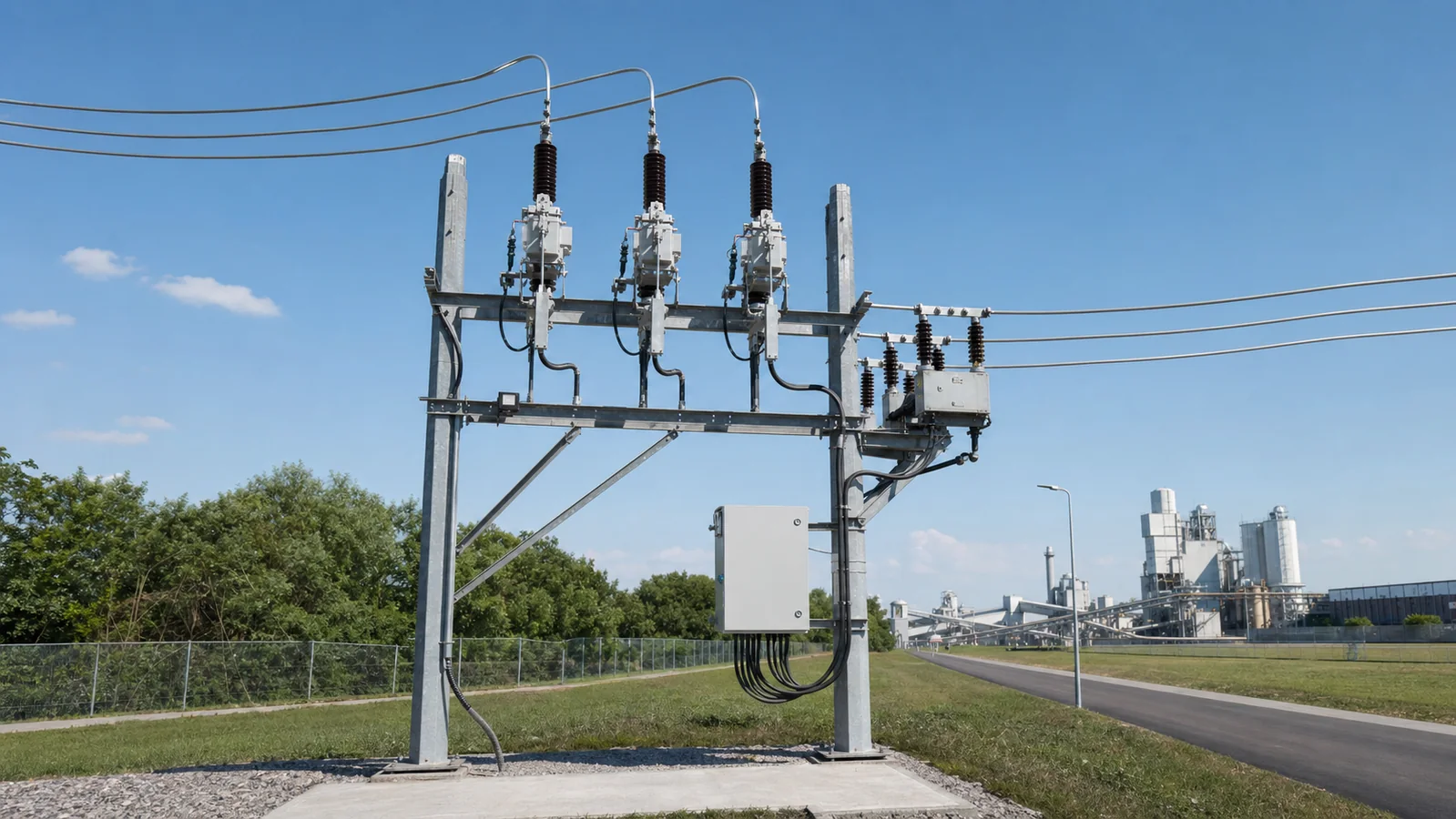
A user boundary switch is a medium-voltage switching and protection assembly installed near the connection between a public distribution feeder and a customer’s incoming network. In the XIYA POWER configuration, a vacuum circuit breaker works with phase-current sensing, zero-sequence sensing, PT supply or voltage sampling, and an FDR controller. Together, these layers can identify and isolate configured user-side faults while providing event and status information.
The name does not define every boundary around the connection. The physical connection point, protection zone, equipment ownership, operating authority, revenue-metering point, and safe-work isolation point may be close together, but they are established by different documents. A product cannot assign legal responsibility or operating permission by itself.
| Boundary | Practical Meaning | Defined By |
|---|---|---|
| Physical connection | Where the feeder and customer incoming circuit meet | Approved single-line, site layout, and connection drawing |
| Protection zone | Which faults the controller is configured to detect and clear | Protection study and approved setting sheet |
| Ownership | Who owns equipment on each side | Connection agreement and asset records |
| Operating authority | Who may trip, close, isolate, or apply locks | Utility and site operating procedures |
| Revenue metering | Where billing quantities are measured | Metering agreement and approved metering scheme |
| Safe isolation | The points proved dead, isolated, secured, and earthed for work | Approved safety procedure and permit-to-work system |
This is a review aid, not an operating instruction. Only authorized personnel should access records or equipment, and any test or switching action must follow the approved site and utility procedure.
| Symptom | First Test | Likely Cause | Next Action |
|---|---|---|---|
| Boundary breaker is open with a ground-fault indication | Read the event record and compare the residual-current channel with the approved setting sheet | Customer-side earth fault, sensing issue, or incorrect setting/data mapping | Hold reclosing; inspect the defined protection zone and follow the approved fault-clearance process |
| Phase overcurrent event is recorded | Compare phase-current records, upstream events, and the coordination study | Customer-side interphase fault, overload, upstream disturbance, or coordination issue | Identify the faulted zone before changing any setting or closing sequence |
| Controller is powered but voltage sampling is absent | Check PT secondary supply, fuses, terminals, and configured input mapping | PT supply interruption, wiring issue, wrong ratio, or configuration mismatch | Correct only against the approved PT and controller drawings, then repeat the authorized functional check |
| Remote command is received but no operation follows | Review local/remote state, interlocks, control power, command log, and communication quality | Active interlock, low control power, disabled remote authority, or mapping error | Resolve the blocking condition through the approved control and communication schedule |
| Local protection operates but no event reaches DA/SCADA | Compare the local event log with modem, protocol, address, and master-station records | Communication outage or data-model mismatch | Keep protection and communication investigations separate; correct the link without altering protection settings |
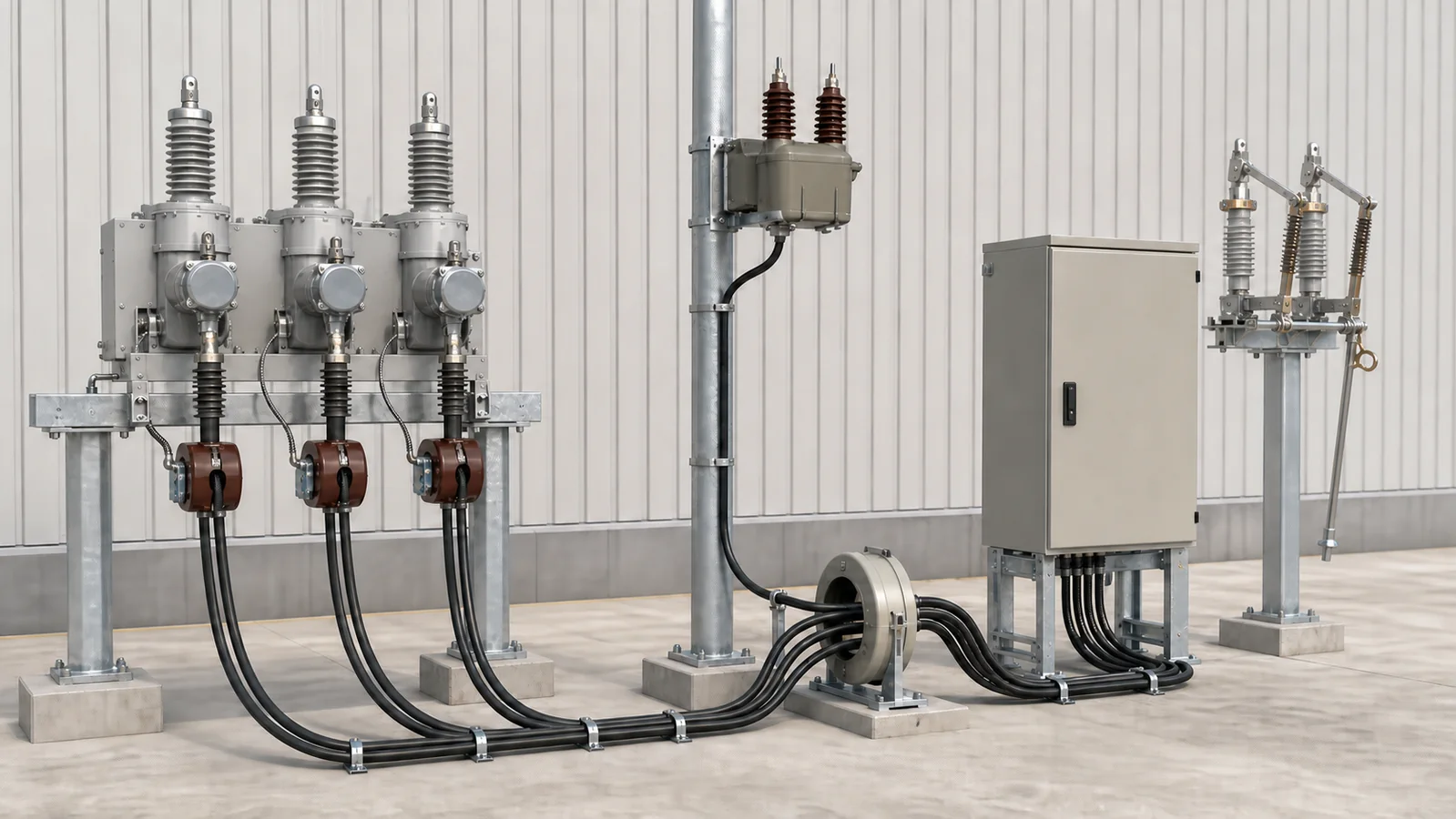
The switching body is only one layer. The XIYA POWER User Boundary Switch page presents ZW20-12 / ZW139A-12 configurations for 10 kV overhead customer demarcation applications using a 12 kV standard series. Its published architecture includes:
The optional isolator is important because an open circuit breaker is not automatically a visible-isolation point. Safe work requires the exact isolation, proving-dead, locking, and earthing steps specified for the site.
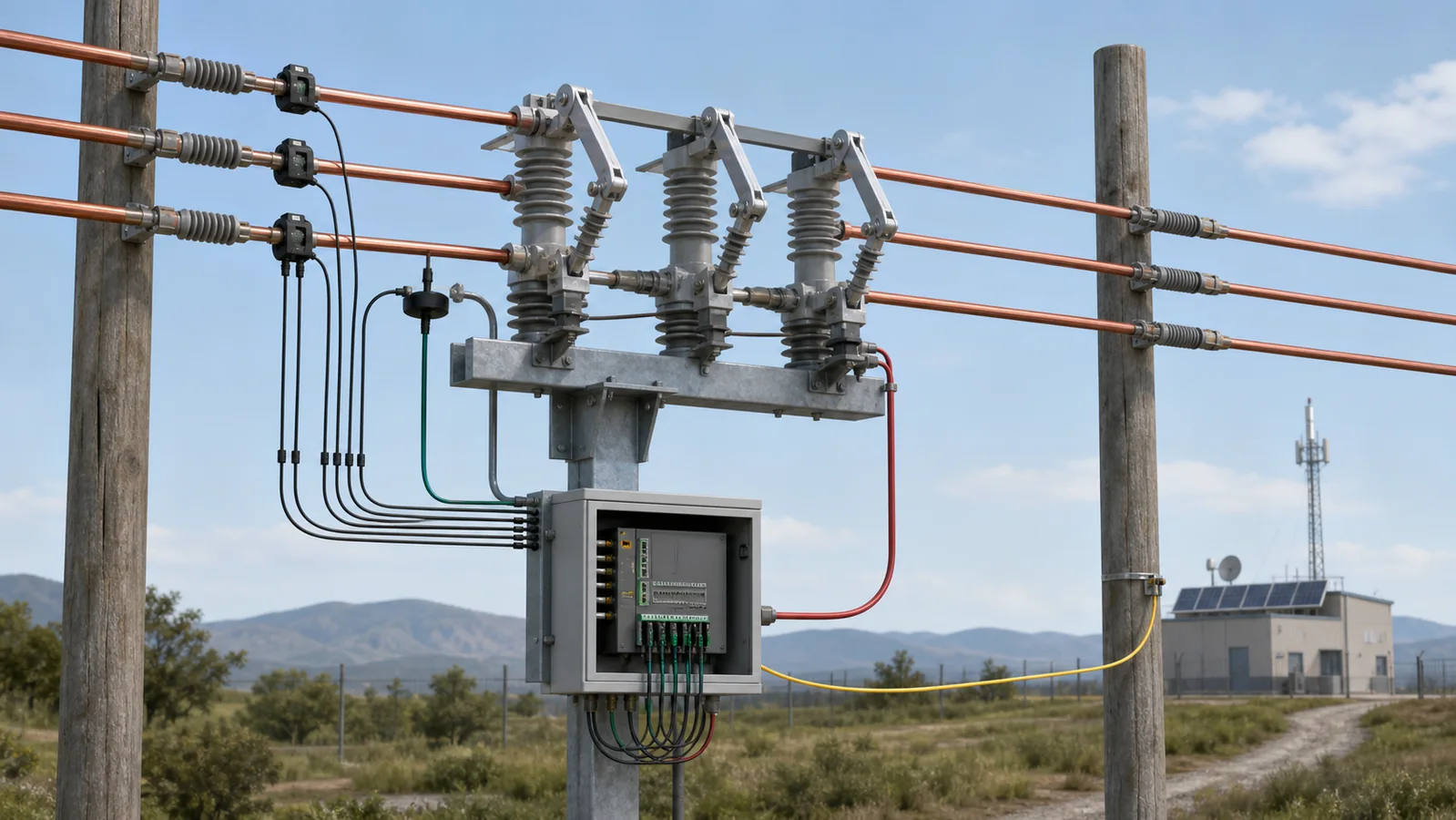
Four paths pass through or around the boundary device. Reviewing them separately prevents one interface from being mistaken for another.
Power path. Current flows from the upstream feeder through the breaker to the customer incoming circuit. Voltage class, normal current, short-circuit duty, conductor connections, and installation layout belong to this path.
Protection-signal path. Phase CT, zero-sequence CT, and PT signals enter the controller. Their ratios, classes, polarity, grounding, wiring, and configured channel mapping must match the protection study and approved diagrams.
Trip and close path. The controller sends an electrical command to the breaker operating mechanism. Control supply, trip/close coils, auxiliary contacts, local/remote selection, interlocks, and mechanical state determine whether the command can be completed.
Communication path. A modem or wired interface can carry events, measurements, switch status, alarms, and authorized remote commands between the controller and DA/SCADA. Protocol, addresses, data points, time synchronization, cybersecurity controls, and remote operating permissions are project inputs, not standard defaults.
The wider Smart Grid equipment group helps place this device among other sensing, protection, and automation equipment. A boundary device protects one defined customer connection; it should not be assumed to use the same protection philosophy as an automatic vacuum circuit recloser located on a feeder.
The desired outcome is simple: a fault in the customer network should be cleared as selectively as the approved protection design allows, so a healthy upstream feeder or adjacent branch is not unnecessarily interrupted. The engineering required to obtain that outcome is not simple.
For an earth-fault function, the neutral grounding method determines the expected fault-current behavior. The zero-sequence CT arrangement and controller setting must be based on that system data and coordinated with upstream and downstream protection. A setting copied from another installation may be insensitive, unstable, or non-selective.
For an interphase fault, the breaker interruption duty, phase CT inputs, controller logic, and upstream feeder protection must be studied together. The live XIYA POWER page describes a configured scheme in which the boundary controller can keep a faulty customer branch open during feeder restoration. That is a product-application description, not a universal utility sequence. The actual trip, lockout, reclose, and restoration logic comes from the approved project scheme.
IEC 62271-100:2021 covers alternating-current circuit breakers above 1 kV within its published scope. It does not define ownership boundaries, utility operating rules, protection settings, communication protocols, or safe-isolation procedures. Those remain project and operator responsibilities.
This example is representative engineering reasoning, not a XIYA POWER project, utility case, commissioning event, or measured field record.
Assume a boundary breaker opens and the controller records residual-current pickup on a customer branch. The first question is not whether the breaker can close; it is whether the recorded signal represents a fault inside the defined protection zone.
The protection engineer compares the event current and duration with the approved setting sheet, checks the phase-current channels, verifies the CT/ZCT mapping, and reviews the upstream event timeline. The maintenance team inspects the customer cable and equipment using the authorized isolation and test procedure. The operator confirms whether any reclose inhibit, lockout, or remote-control restriction remains active.
Three different outcomes are possible. Evidence may confirm a customer-side insulation fault; it may reveal incorrect sensing or channel mapping; or it may show a disturbance outside the intended zone. Each outcome requires a different corrective action. Closing before those distinctions are made can restore supply into an uncleared fault or conceal a protection defect.
This decision path is why the neutral grounding declaration, CT/ZCT data, setting sheet, event records, and operating procedure must agree before the equipment enters service.
The Circuit Breakers product group explains the interrupting layer, but a boundary-switch RFQ also needs the system around it:
| Activity | Tool or Evidence | Acceptance Source | Result Handling |
|---|---|---|---|
| Visual and dimensional review | Approved drawings, photographs, and calibrated dimensional tools | Project specification and released layout | Record deviations and issue a corrective action before release |
| Insulation condition | The insulation test method authorized for the installed circuit | OEM manual, project specification, and approved procedure | Retain the result in the test record |
| Breaker current path | Contact resistance measurement where required | OEM manual and approved factory or baseline data | Investigate connections and mechanism condition before adjustment |
| Protection functions | Controlled secondary-injection or approved functional test | Setting sheet, coordination study, and test procedure | Verify pickup, timing, outputs, and lockout without inventing limits |
| Control and communication | I/O check, event-log review, and protocol test tools | Point list, communication schedule, and operating philosophy | Separate mapping defects from protection defects and document corrective action |
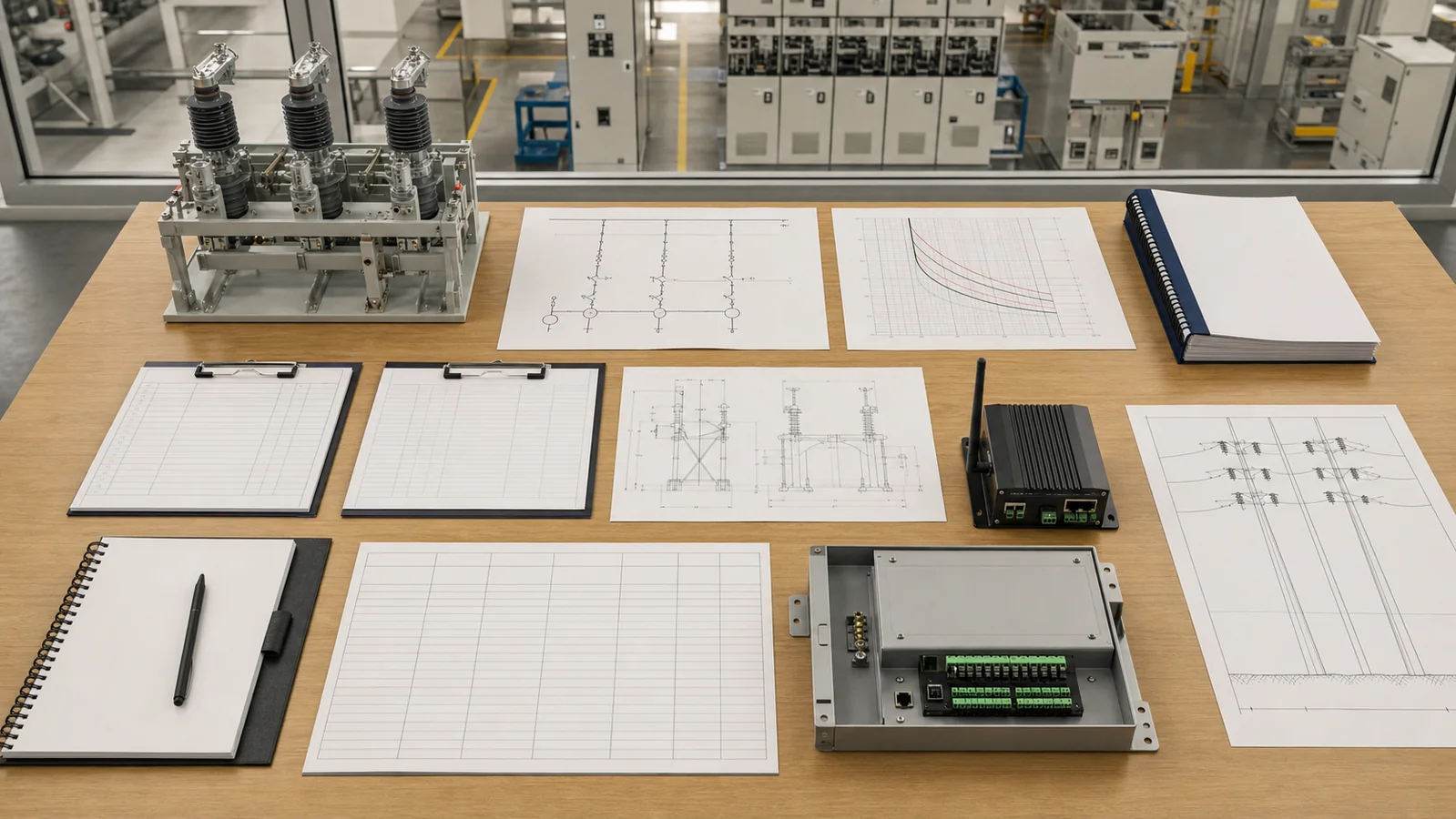
A useful submission combines equipment data with responsibility and approval data. Include the single-line diagram, fault-level and coordination studies, neutral grounding declaration, load profile, CT/ZCT/PT schedule, controller function list, preliminary setting responsibility, communication point list, pole layout, earthing arrangement, environmental conditions, document register, inspection plan, and quantity.
Also identify who approves drawings, who supplies final settings, who may operate the device, who owns the communication link, and which party performs factory and site acceptance. These responsibilities cannot be inferred from the words user boundary switch.
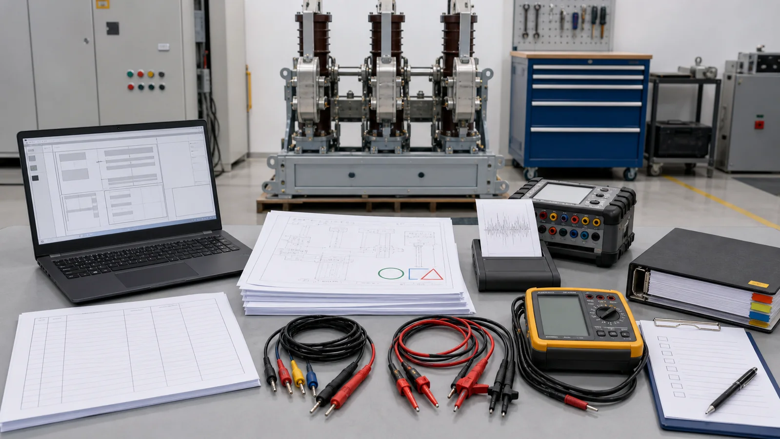
Before manufacturing release, close every open technical item. Before energization, confirm the installed primary circuit, sensing polarity, controller configuration, trip/close path, local/remote permissions, event records, and required interlocks through the approved test plan. Store the released drawings, setting file, test record, and change history together.
The switching body may be a vacuum circuit breaker, but the boundary package also includes sensing, controller logic, project-specific coordination, and often communication. The package role is defined by the complete approved scheme.
Not automatically. Safe isolation depends on the approved procedure and may require a separate visible isolation point, proving dead, securing against operation, and applying earths. The breaker indication alone does not replace those steps.
Compatibility cannot be decided from the product name. The grounding method controls expected earth-fault current and therefore affects sensing, CT/ZCT selection, settings, and upstream coordination. Submit the actual system study for review.
That behavior must be confirmed from the approved controller architecture and configuration. Local protection and external communication are separate paths, but loss-of-communication alarms, remote permissions, and any blocking logic remain project-specific.
The project must assign this responsibility to a qualified protection engineer and identify the approving utility or owner. Settings should be based on the network study, grounding method, sensing data, coordination requirements, and released operating philosophy.
A user boundary switch creates a controllable protection point at a customer connection. It does not by itself define ownership, operating authority, metering responsibility, or safe isolation. A reliable project aligns the breaker duty, sensing package, controller logic, communications, physical layout, setting sheet, and operating agreements before the equipment is ordered or energized.



