Quotation form
Send an inquiry
Start with the basics. Our team can follow up for missing drawings, standards or packing details.
Submitted details are used only for quotation, technical review and project communication.

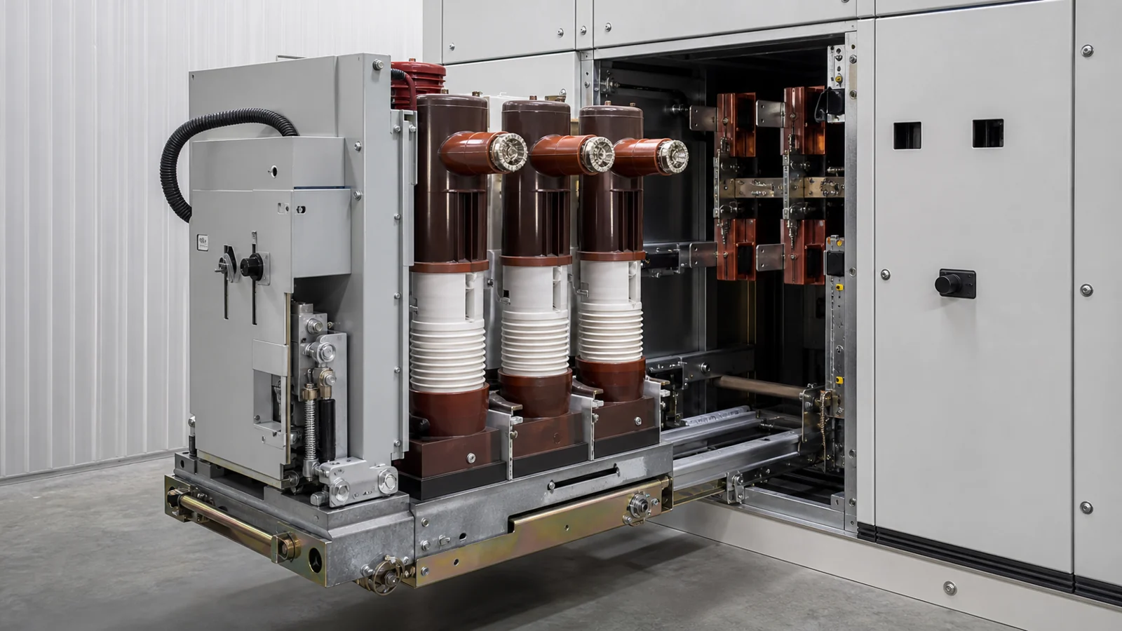
A vacuum circuit breaker (VCB) is a medium-voltage switching and protection device that uses vacuum interrupters. Its permitted load, fault-making, fault-breaking, and operating duties are those stated in the approved equipment data and project protection arrangement; they are not generic values that apply uniformly across VCB families or installations.
Setting the duty boundary matters because disconnect switches, load break switches, and circuit breakers serve distinct functions, and no single device covers all three roles by default. A disconnect switch serves an isolation role under the approved operating procedure. A VCB in the open position must not automatically be treated as the required isolation point; project safety rules, the one-line arrangement, interlocks, and OEM documentation determine the isolation method.
A load break switch occupies the middle position in this hierarchy: it can interrupt and establish load current at defined levels but is not designed for the high-asymmetric fault currents a circuit breaker must handle, and it typically lacks the automatic trip interface driven by a protection relay. Applying a load break switch where a fault-interrupting, relay-tripped device is required by the protection study leaves the circuit without adequate fault protection—a distinction the project engineer must confirm in writing before finalizing equipment selection.
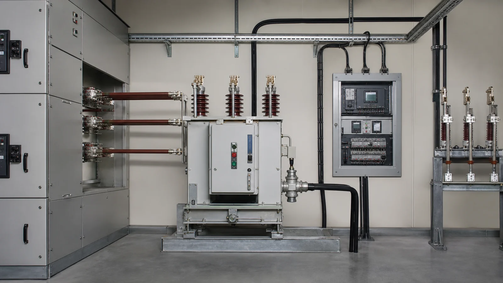
FIG-01: Illustrative position of a vacuum circuit breaker within a medium-voltage protection arrangement, showing its relationship to upstream isolation devices and downstream load break switching equipment.
The vacuum interrupter is a sealed envelope—typically ceramic with metal end plates—enclosing a fixed contact and a moving contact separated by a high-vacuum environment. When the contacts part under alternating current, the arc that forms between the separating surfaces is sustained only by metal vapor driven from the contact material itself. Because there is no gaseous medium to maintain the plasma column, the arc extinguishes naturally at the first current zero—the moment each half-cycle when the alternating waveform passes through zero amplitude—without reignition under most medium-voltage conditions.
The practical consequence of this interruption physics is that the contact travel required to achieve adequate post-arc dielectric recovery is short compared with older air-blast or bulk-oil designs. That short travel reduces the energy the mechanism must supply and supports fast operating times. The specific interrupting capability of a given vacuum interrupter is a function of contact material, geometry, and vacuum integrity; the OEM data sheet and factory type-test certificate are the authoritative references for any particular product, and no performance claim should be accepted without them.
The operating mechanism stores sufficient energy to drive the moving contact through its full opening travel in milliseconds, before the arc can deposit significant thermal energy into the interrupter components. Spring-charged designs—using either a single stored-energy spring or independent close and trip springs—are the most common arrangement at medium voltage. Magnetic actuator designs, based on a bistable electromagnetic coil, are also available and offer fewer moving parts. Both types accept an electric motor that recharges the spring automatically after each operation, returning the mechanism to a ready state without manual intervention.
The mechanism is coupled to the moving contact through an insulating operating rod that crosses the high-voltage boundary of the breaker pole assembly. The insulating rod must maintain rated clearance and creepage distances for the voltage class of the installation. Its material condition and dimensional integrity are inspection items defined in the OEM maintenance schedule, and they should be confirmed at the intervals that schedule specifies—never assumed to be acceptable based on calendar age alone.
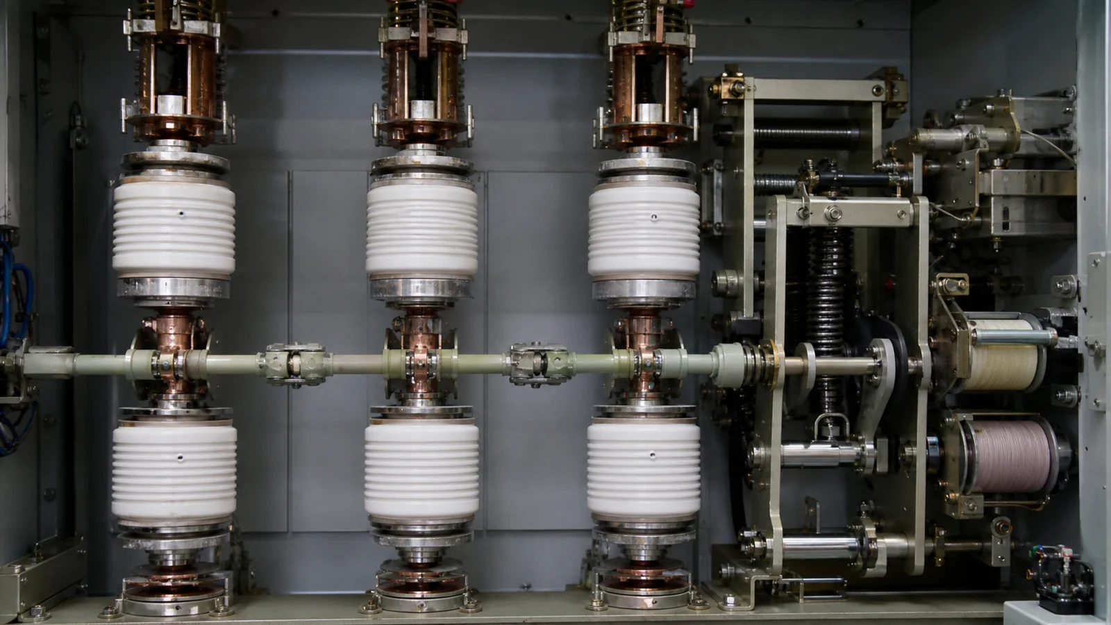
FIG-02: Illustrative cross-section of a vacuum circuit breaker pole, showing the sealed vacuum interrupter envelope, moving contact stem, insulating operating rod, and spring-charged mechanism assembly.
A VCB responds to trip and close commands issued by external control logic. The primary source of automatic trip commands is the protection relay—a numerical device programmed with overcurrent (ANSI function 50/51), earth-fault (ANSI 50N/51N), or other protection functions defined in the project’s protection coordination study. The relay evaluates current transformer signals against configured pickup settings and time-delay curves, then issues a trip signal to the breaker’s trip coil when a defined threshold is exceeded. The breaker mechanism responds by releasing stored spring energy and driving the contacts open.
This relay-commanded trip path is the functional distinction that positions a VCB above a load break switch in the protection arrangement. XIYA POWER’s medium-voltage circuit breaker range is designed to interface with numerical protection relays through standard trip and close coil circuits; relay selection, current transformer ratio, and protection settings are determined by the project protection engineer and are not part of the standard breaker supply unless explicitly stated in the order specification.
The table below summarizes the key functional differences among the three device types discussed in this article. Specific ratings must always be confirmed from the applicable product data sheet.
| Feature | Disconnect Switch | Load Break Switch | Vacuum Circuit Breaker |
|---|---|---|---|
| Interrupting duty | De-energized switching only | Load current at rated LBS level | Full fault current at rated breaking capacity |
| Automatic trip interface | None | None in standard designs | Protection relay trip coil |
| Visible isolation gap | Typically provided | Depends on product design | Not standard; requires separate isolator |
| Drive method | Typically manual | Manual or motorized | Motor-charged spring mechanism |
| Primary application | Safe isolation for maintenance access | Sectionalizing and load transfer | Fault protection and automatic switching |
| Type-test reference standard | Product-specific standard | Product-specific standard | IEC 62271-100 |
Many VCB configurations use withdrawable truck modules designed to mate with a complete switchgear cabinet. The approved general arrangement defines pole assemblies, mechanism, primary contacts, secondary connector, shutters, interlocks, cable interfaces, and any connected, test, or isolated positions. These details must not be inferred from the VCB label alone.
Dimensional and electrical compatibility between a breaker truck and a cabinet must be established from matched equipment drawings before procurement is finalized. A breaker truck built to one manufacturer’s dimensional standard does not automatically fit a cabinet built to a different standard, even when voltage and current ratings appear similar. The secondary plug wiring—carrying trip and close coil circuits, auxiliary contact signals, and in some configurations CT secondary leads—must match the pin assignments defined in the switchgear scheme diagrams supplied by the cabinet manufacturer.
The interrupting performance of a VCB installed in a cabinet is bounded by its approved rated data and project conditions. Applicable circuit-breaker standards and editions should be confirmed through the IEC Webstore, the project specification, and approved product documents. Any compliance or capability conclusion must use the evidence required by that project’s approval package.
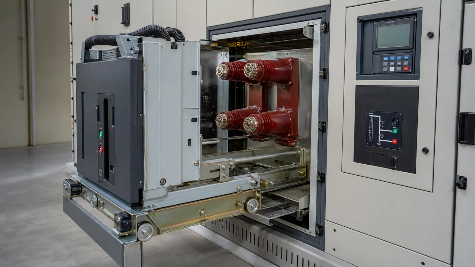
FIG-03: Illustrative review diagram showing the interface between the VCB truck, protection relay, secondary plug wiring, and switchgear cabinet shutter-interlock positions during racking travel.
Acceptance should use the project specification, approved drawings and settings, OEM manuals, and the inspection or test records required by the order. These sources define the ratings, control interface, maintenance limits, insulation checks, and any commissioning evidence applicable to the supplied configuration.
These four documents together establish that the installed breaker matches the specified rating, has been tested to the required levels, and carries protection settings that correspond to the coordination study. Verbal assurances or catalog data sheets are not a substitute for signed test records when the project specification requires formal commissioning evidence.
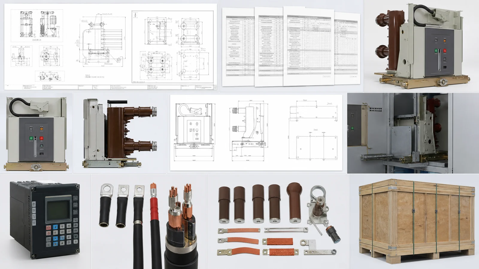
FIG-04: Illustrative document package for VCB procurement and acceptance review, comprising the project specification, OEM product manual, factory and site insulation test certificates, and commissioning test record.
The table below is illustrative only. All observations must be evaluated against the OEM service manual, the site commissioning test record, and the applicable safety rules before any maintenance action is initiated.
| Symptom | First Test | Likely Cause | Next Action |
|---|---|---|---|
| Breaker fails to close on command | Measure control voltage at closing coil terminals with dc voltmeter | Low battery bus voltage, open control fuse, or secondary plug not fully seated | Verify dc bus level; inspect fuse; confirm truck racking position |
| Breaker trips immediately after closing | Secondary injection test on protection relay using calibrated relay test set | Relay pickup set below load current, or CT polarity reversal | Review relay settings file with protection engineer before re-energizing |
| Contact resistance reading above established baseline | Contact resistance measurement using calibrated micro-ohmmeter at rated test current | Contact surface erosion, oxidation film, or mechanical misalignment | Compare to OEM published limit; consult service manual before deciding on contact replacement |
| Spring-charge motor runs continuously but mechanism does not reach charged state | Rack out, de-energize, and inspect limit-switch position and motor coupler condition | Limit-switch misadjustment or mechanical coupler failure | Adjust or replace per OEM service instruction; record in maintenance log |
| Partial discharge indication from installed monitoring system | Scheduled PD measurement under energized conditions per site protocol | Contamination on insulating surfaces, surface tracking initiation, or vacuum envelope degradation | Perform insulation resistance test; remove breaker from service; consult OEM before re-energization |
Specifying engineers should confirm the following parameters when preparing a request for quotation. Parameters not included in the RFQ default to the OEM standard product option, which may not satisfy the project requirement.
| Parameter Category | Required RFQ Input | Source Document |
|---|---|---|
| System voltage class | Rated maximum voltage (kV), rated power-frequency withstand (kV rms), rated lightning impulse withstand (kV peak) | Project specification |
| Continuous current | Rated normal current (A) at design ambient temperature | Load-flow study |
| Short-circuit rating | Rated short-circuit breaking current (kA rms symmetrical) and rated short-time withstand current | System fault-level study |
| Operating frequency | 50 Hz or 60 Hz | Project specification |
| Control voltage | DC bus voltage class (V) and acceptable tolerance band for trip and close coils | Station battery design documents |
| Mechanical endurance class | Class M1 or M2 per applicable product standard | Project specification |
| Cabinet interface | Truck dimensional standard, busbar stab geometry, secondary plug connector type and pin assignment | Switchgear cabinet general arrangement drawing |
| Protection relay compatibility | Relay model, trip coil voltage, close coil voltage, CT ratio and burden requirements | Protection design package |
| Auxiliary contacts | Quantity and type (NO/NC) required for interlocking, position indication, and remote monitoring | Control and interlock drawing |
| Environmental and site conditions | Installation altitude, ambient temperature range, indoor or outdoor, seismic zone, humidity classification | Site data sheet |
A vacuum circuit breaker protects a medium-voltage circuit by interrupting current automatically when the connected protection relay detects an abnormal condition—typically overcurrent or earth fault—that exceeds the configured threshold. The relay evaluates current transformer signals against its pickup and time-delay settings, then issues a trip signal. The breaker mechanism responds within its rated operating time, and the vacuum interrupter extinguishes the arc at the next current zero. The specific fault types addressed are determined by the relay functions configured in the protection coordination study, not by the breaker hardware in isolation.
An open vacuum circuit breaker does not provide a visible, physically confirmed open gap in the way a dedicated isolation device does. Safety rules governing medium-voltage work require a visible or positively verified open gap—and typically a mechanical lock—before personnel are permitted to work on de-energized conductors downstream. A VCB may also reclose under automated reclosing logic or inadvertent control-circuit actuation, whereas a locked-open isolator provides a mechanical barrier against re-energization. For isolation duty, a correctly rated and documented disconnect switch must be used; the project specification and OEM documentation determine whether any specific device qualifies for that role.
IEC 62271-100 specifies the rated characteristics, classifications, and type-test sequences—including making and breaking capability tests, short-time withstand tests, and mechanical endurance tests—that alternating-current circuit breakers must pass to demonstrate their rated performance under recognized laboratory conditions. A breaker supplied with valid type-test certificates issued under this standard has been tested at a qualified facility to interrupt its rated fault current through the sequences the standard prescribes. Confirming that the edition cited in the test certificates matches the edition required by the project specification is a routine step in procurement review and should not be deferred until the equipment arrives on site.
Operating-life tracking must follow the approved breaker data and OEM maintenance instructions. Where the selected breaker records operation counts, fault operations, contact wear, or maintenance limits, those records should be reviewed under the owner’s maintenance program rather than converted into a universal interval.
A complete specification inquiry should include the system voltage class and insulation level, the maximum continuous load current, the available fault level at the installation point, the control bus voltage and station battery details, the switchgear cabinet dimensional and interlock standard, the protection relay model intended for the application, and any special environmental or seismic requirements applicable to the site. These parameters are listed in the RFQ input table above. Providing complete data at the inquiry stage allows the XIYA POWER engineering team to confirm product compatibility and identify any discrepancy between the standard product range and the project requirements before equipment is ordered and lead time is consumed.