Quotation form
Send an inquiry
Start with the basics. Our team can follow up for missing drawings, standards or packing details.
Submitted details are used only for quotation, technical review and project communication.

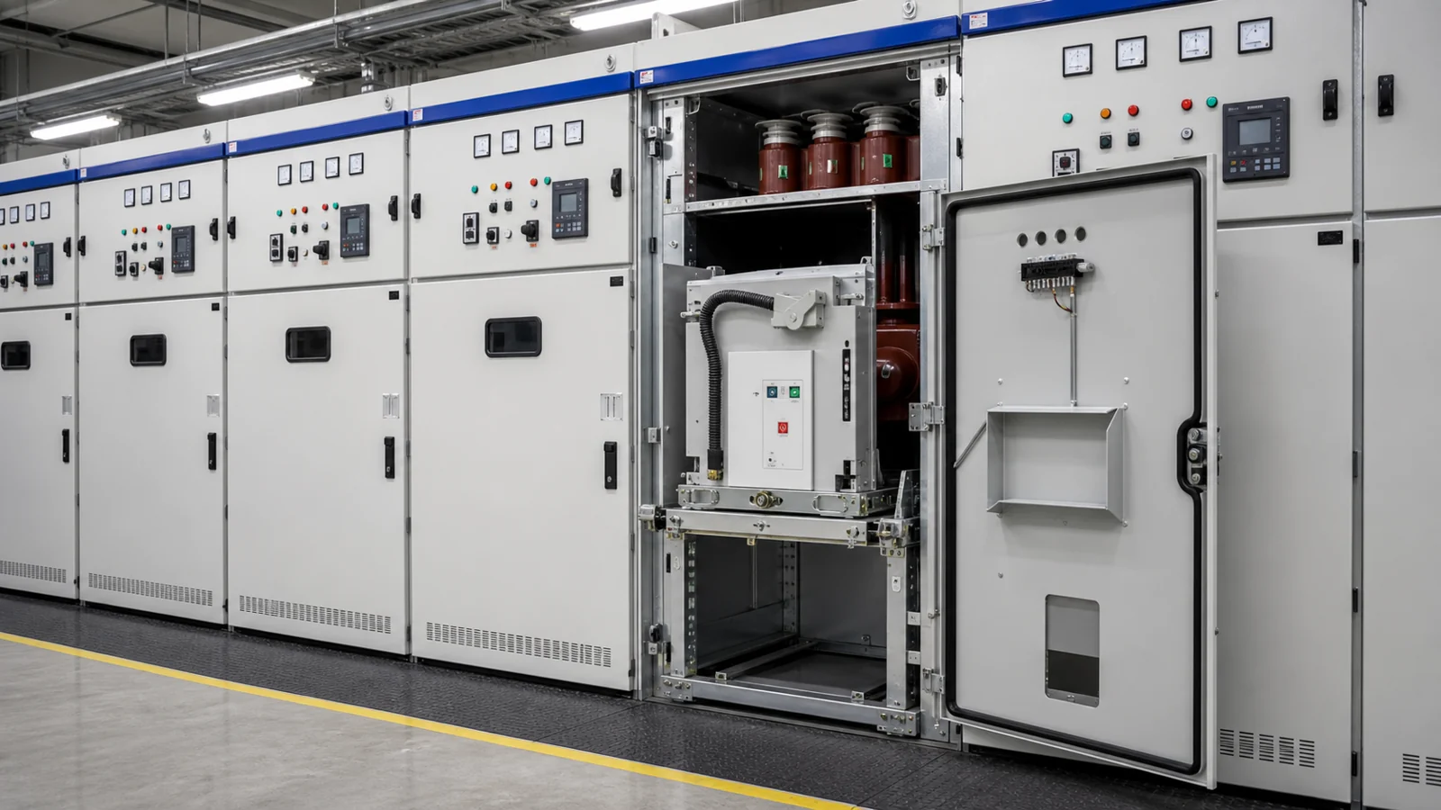
KYN28 switchgear designates a family of metal-clad, withdrawable medium-voltage distribution cabinets manufactured to house a vacuum or SF₆ circuit breaker on a withdrawable truck, together with busbars, cable terminations, protection relays, and the mechanical and electrical interlocks that coordinate those elements into a single enclosed assembly. The designation identifies a cabinet construction category, not a fixed performance rating or a universal specification. Actual voltage class, rated current, short-circuit withstand level, protection scheme, and physical arrangement are determined by the project specification and the manufacturer’s product data sheet for the specific order. XIYA POWER supplies KYN28 metal-clad switchgear as part of its complete switchgear cabinet range, and individual cabinet parameters must be confirmed against project documents before procurement or installation.
The KYN28 designation places the cabinet within the metal-clad class, which means every live part—busbar, circuit breaker, and cable connection—is enclosed within a grounded metallic partition. That structural boundary distinguishes a metal-clad cabinet from a metal-enclosed or open-type panel and is the starting point for understanding what KYN28 switchgear is and is not.
Within that boundary, the cabinet is a mechanical and electrical host. It does not independently determine which breaker it accepts, which protection relay it carries, or which busbar rating it serves. Those parameters come from the one-line diagram, the protection coordination study, the project’s earthing philosophy, and the manufacturer’s approved drawing set. A buyer who understands this boundary avoids two common misreadings: treating the KYN28 label as a performance guarantee, or assuming that a cabinet supplied from one project is interchangeable with an identically labeled cabinet specified on a different project.
The family encompasses indoor, floor-standing cabinets intended for switchrooms with controlled access. Individual cabinets are normally assembled into a switchboard lineup, with a common high-voltage busbar running through each cabinet and low-voltage wiring linking protection, metering, and control across the row. The lineup boundary—number of feeders, bus section arrangement, and any bus coupler positions—is defined by the project single-line diagram, not by the cabinet family designation.
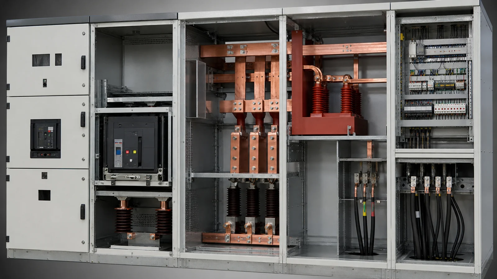
FIG-01: KYN28 cabinet functional zones showing the four primary compartments, their grounded metallic separations, and the position of the withdrawable truck in relation to the busbar and cable chambers.
A KYN28 cabinet is internally divided into four metallic compartments. Each compartment is physically separated from the others by grounded steel partitions, so that work in one zone does not expose personnel to live conductors in an adjacent zone, provided appropriate isolation procedures have been followed. The four compartments are:
| Compartment | Primary contents | Key interface |
|---|---|---|
| Busbar chamber | Main copper busbars, bus-side shutters | Busbar joint to adjacent cabinets and to upper stabs of withdrawable truck |
| Breaker (truck) chamber | Withdrawable circuit breaker truck | Upper and lower shutter mechanisms, secondary plug-and-socket connector |
| Cable chamber | Cable terminations, current transformers, voltage transformers (where fitted), earthing switch | Cable glands, CT secondary terminals, earthing switch interlock |
| Low-voltage (relay/control) compartment | Protection relay, metering, control wiring, auxiliary power supply | Secondary connector, external control cables, HMI door panel |
The arrangement ensures that the high-voltage busbar, the interrupter, and the cable connection are each in separate enclosed spaces. Access to any HV compartment follows a defined sequence of operations that depends on the interlock system and the project-specific safety rules—not on the table above, which is illustrative of the general family arrangement.
The withdrawable truck carries the circuit breaker and may provide connected, test, and isolated positions according to the approved design. Mechanical guides, position indicators, shutters, and electrical interlocks are configuration-specific; their functions and operating sequence must be confirmed from the approved general arrangement, interlock logic, and OEM instructions.
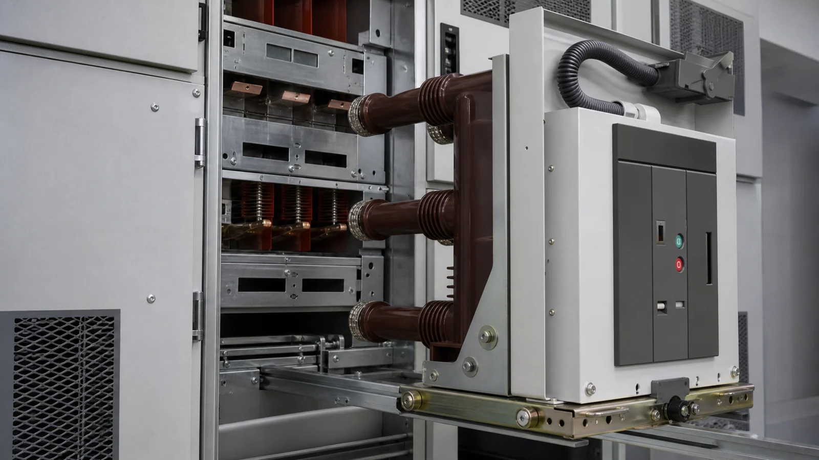
FIG-02: Withdrawable breaker truck showing the upper and lower stab contacts, shutter actuation sequence, and the secondary plug-and-socket connector that transfers protection and control signals between the fixed cabinet and the removable truck.
The secondary connector is the low-voltage interface between the truck and the cabinet. When the truck is racked to the connected or test position, the secondary plug engages and the protection relay receives current transformer and voltage transformer signals from the primary circuit. When the truck is withdrawn, the secondary connector separates, isolating the relay from primary signals without interrupting low-voltage auxiliary supply to the cabinet—a detail that matters for protection schemes that must remain energized during truck movement. The exact secondary connector design and pin assignment must be confirmed from the manufacturer’s approved wiring diagram for the specific order.
The busbar chamber hosts the main three-phase busbars and the bus-side spring-loaded shutters that close automatically when the truck is not in the connected position. The busbar rating—current, voltage, and short-time withstand—is a project parameter confirmed in the equipment schedule. The busbars run continuously through the cabinet row; the joint method and torque values are specified in the manufacturer’s installation manual and must not be assumed from generic references.
The cable chamber at the bottom of the cabinet accommodates medium-voltage power cables entering from below (in most indoor arrangements), together with any current transformers on the cable cores and, where specified, a voltage transformer on the cable-side conductors. An earthing switch is typically located in this chamber and is interlocked to prevent closure onto an energized cable. Again, the earthing switch ratings and interlock logic are project-specific items confirmed by the approved drawing set.
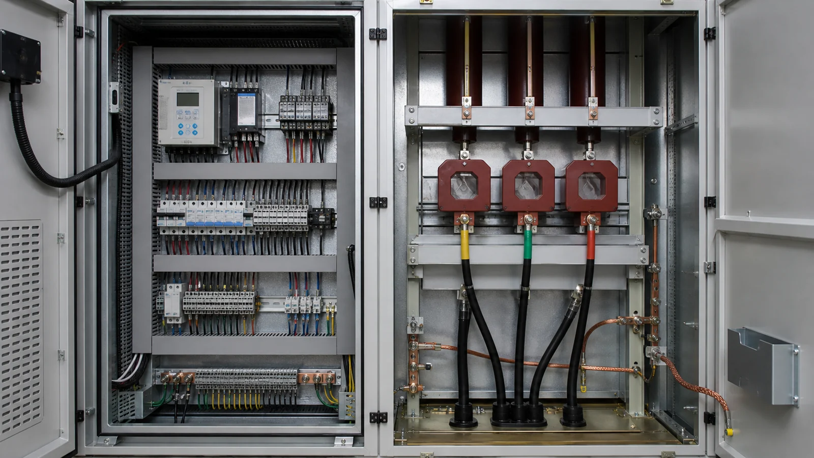
FIG-03: Protection-relay compartment and cable chamber review points, indicating CT secondary terminal blocks, voltage transformer secondary fusing, cable screen earthing arrangements, and relay front-panel access for functional testing.
The low-voltage compartment houses the protection relay and associated metering, control switches, indicators, and auxiliary wiring. The relay type and setting group are determined by the protection coordination study, which is a project document separate from the cabinet specification. Common functions for a feeder cabinet—overcurrent, earth fault, and where required, distance or differential elements—are relay functions, not cabinet-family properties. A buyer should not assume that a KYN28 cabinet arrives with a specific relay or with settings already confirmed; both are project-specific deliverables.
Control wiring exits the cabinet through a low-voltage gland plate, typically in the cable compartment or the base, and connects to the substation control and monitoring system. Secondary cable types, screen earthing arrangements, and terminal numbering follow the project’s secondary wiring specification and the approved wiring diagram.
Acceptance of a KYN28 cabinet—whether at factory or on site—should be referenced to the project specification, approved drawings, the OEM installation and maintenance manual, and the inspection or test records required by the order. The exact document set and acceptance criteria are project-specific; no generic checklist replaces the agreed purchase and approval package.
Buyers who review only the cabinet nameplate or data sheet without cross-referencing these four sources risk accepting a cabinet that does not conform to project requirements or one for which test evidence is incomplete.
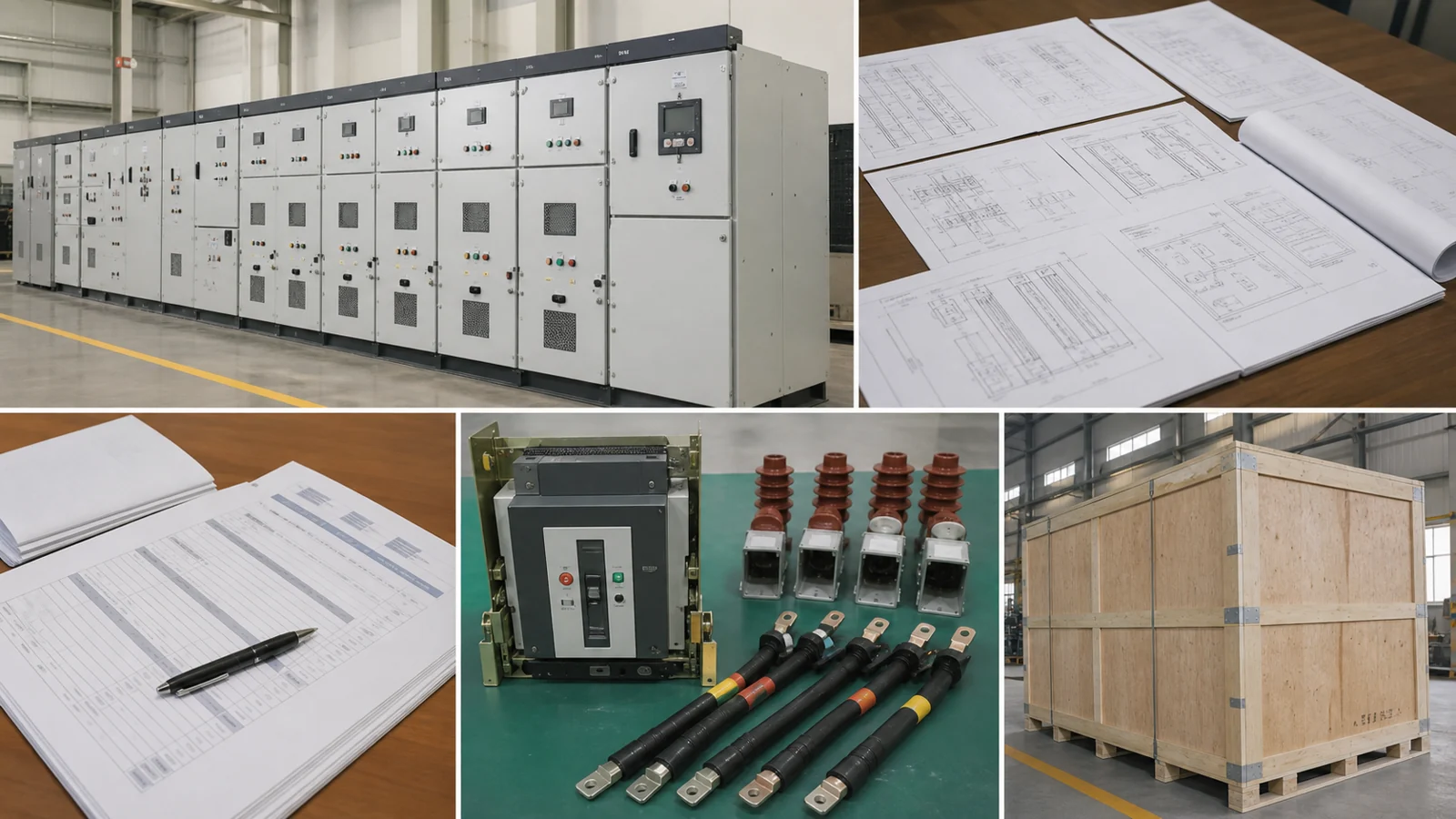
FIG-04: KYN28 RFQ and approval document package illustrating the relationship between the project one-line diagram, equipment schedule, protection relay specification, approved general arrangement drawing, and factory test record as inputs to a complete procurement submission.
Applicable metal-enclosed-switchgear standards and their required editions should be confirmed through the IEC Webstore, the project specification, and the approved product documentation. Any compliance conclusion for a specific cabinet must be supported by the evidence required in that project’s approval package.
The following table is illustrative only. It identifies symptom patterns that practitioners sometimes encounter during commissioning or routine inspection of metal-clad switchgear of this class. It does not represent measured results, reported field events, or certified diagnostic procedures. Any actual investigation must follow the project-specific maintenance procedure and the OEM manual.
| Symptom | First test | Likely cause (illustrative) | Next action |
|---|---|---|---|
| Breaker fails to rack to connected position | Verify truck position indicator and guide rail alignment visually | Mechanical misalignment or deformed guide rail | Refer to OEM installation manual; do not force |
| Protection relay loses CT signal input | Check secondary connector engagement with truck in test position | Secondary plug not fully engaged, or open CT secondary wiring | Inspect secondary connector pins; measure CT secondary loop resistance |
| Earthing switch will not close | Verify cable-side isolation confirmed and interlock key present | Interlock not released or cable-side still energized | Follow project isolation procedure; do not defeat interlock |
| Insulation resistance below project limit | Re-measure after surface cleaning and with cable disconnected | Surface contamination or moisture in cable chamber | Refer to insulation data sheet; consult OEM manual for drying procedure |
| Shutter does not close on truck withdrawal | Inspect shutter spring and actuator mechanism with HV isolated | Shutter spring fatigue or mechanical obstruction | Refer to OEM spare parts list; do not operate with shutter unconfirmed closed |
| Input item | What to supply | Where it comes from |
|---|---|---|
| Rated voltage (kV) | Project system voltage and insulation level | Project specification / equipment schedule |
| Rated normal current (A) | Busbar and feeder current from load schedule | Load flow study |
| Short-circuit level (kA, duration) | Fault current at the switchboard busbar | Short-circuit calculation report |
| Number and type of functional units | Incomer, bus section, feeder, metering, earthing | Project one-line diagram |
| Protection relay type and functions | Relay model and required protection elements | Protection coordination study |
| CT and VT ratios and accuracy classes | Per IED input requirements | Metering and protection specification |
| Cable entry configuration | Cable quantity, type, and entry direction | Cable schedule and installation drawings |
| Auxiliary supply voltage | AC/DC, voltage level, redundancy | Project auxiliary supply schedule |
| Interlock philosophy | Key interlock scheme diagram | Project safety and isolation rules |
| Environmental conditions | Indoor ambient temperature range and altitude | Site data sheet |
Metal-clad means that all live high-voltage parts—busbars, circuit breaker contacts, and cable terminations—are individually enclosed within grounded metallic compartments separated from each other. This construction type differs from metal-enclosed designs where partitions may be non-metallic or absent between some compartments. The metallic separation limits the spread of a fault event between zones and enables defined access to one compartment without exposing personnel to live conductors in an adjacent one, subject to the applicable isolation and earthing procedures.
Suitability is a project-specific determination, not a property of the cabinet family label. The cabinet family must be evaluated against the project’s rated voltage, fault level, protection scheme, environmental conditions, and installation requirements. XIYA POWER’s KYN28 metal-clad switchgear product page provides family information as a starting point; a complete suitability assessment requires review of the project specification and the manufacturer’s product data for the specific configuration.
The circuit breaker type, interrupting medium, and frame size are matched to the specific truck chamber design of each manufacturer’s KYN28 variant. XIYA POWER supplies medium-voltage circuit breakers designed for use with its switchgear lineup; compatibility must be confirmed against the approved general arrangement drawing and the breaker data sheet for each project. Substituting a breaker from a different manufacturer or a different product generation without engineering verification is not recommended.
Beyond the cabinet enclosure and the withdrawable breaker, a complete lineup specification covers current transformers, voltage transformers, earthing switches, protection and metering relays, auxiliary wiring, busbars, and cable termination hardware. XIYA POWER’s switchgear components section describes component-level items available within its product range. Each component must be specified to match the project’s metering accuracy class, protection relay input requirements, and cable interface, and must be covered by the factory test record.
At minimum, request the approved general arrangement drawing, the approved wiring diagram, the factory acceptance test record documenting routine tests performed on the specific production units, the type test certificates applicable to the cabinet design, and the installation and maintenance manual. Cross-reference the factory test record against the project specification’s stated test requirements before releasing shipment. If insulation resistance or high-voltage withstand test values are required by the project specification, confirm that the test record documents those specific tests and that results are within the limits stated in the project documents—not in a generic data sheet.
XIYA POWER supplies KYN28 metal-clad switchgear as part of its complete switchgear cabinet range. All ratings, configurations, and compatibility confirmations are project-specific. Contact XIYA POWER with your project specification and one-line diagram for a qualified product recommendation.



