Quotation form
Send an inquiry
Start with the basics. Our team can follow up for missing drawings, standards or packing details.
Submitted details are used only for quotation, technical review and project communication.

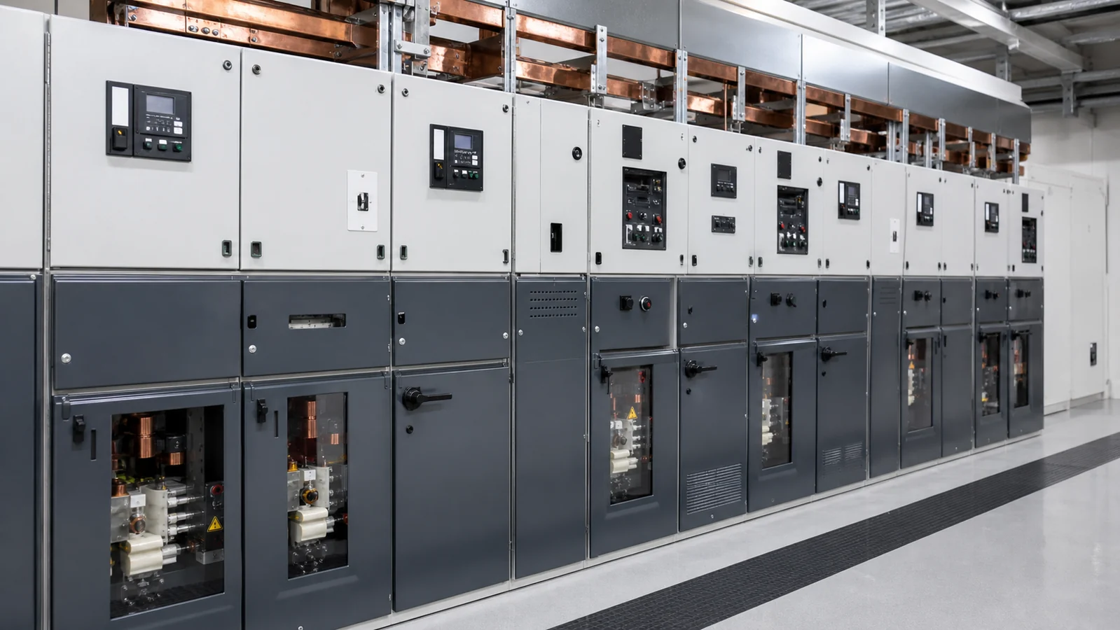
Medium-voltage switchgear is a coordinated assembly of switching devices, protection relays, control equipment, metering instruments, insulation systems, and structural enclosures designed to receive, distribute, and isolate electrical power in the medium-voltage range — broadly 1 kV to 52 kV. The assembly is not simply a metal cabinet; it is a protection and distribution system in which every compartment, interlock, and busbar connection performs a defined electrical and safety function. Understanding those functions is the first step in specifying the correct cabinet family for a substation, industrial plant, or network extension project.
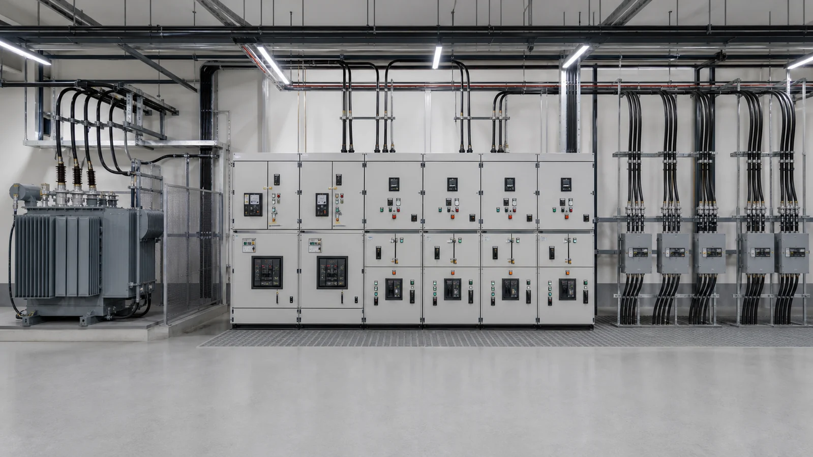
Medium-voltage switchgear sits between the high-voltage transmission network and the low-voltage utilization network. On the supply side it terminates incoming cables or transformer secondaries at voltages expressed in rated classes such as 12 kV, 24 kV, or 40.5 kV. On the load side it feeds distribution transformers, large motors, capacitor banks, or sub-feeders. Where the selected functional unit includes a circuit breaker and protection scheme, it can interrupt the required fault current; other units may provide isolation, load switching, metering, or cable interfaces. The final arrangement must fit the substation room dimensions and project operating duties.
Low-voltage switchgear and distribution boards operate below 1 kV and follow a different set of standards and enclosure conventions. While both LV and MV cabinet families appear on the same product range — the complete switchgear cabinets overview covers both — the protection philosophy, insulation coordination, and arc-flash consequences differ substantially between voltage levels. This article focuses on the MV side.
A well-designed MV cabinet integrates five functional zones, each with distinct roles.
Primary circuit compartment. This zone houses the main switching device — a vacuum circuit breaker, SF₆ breaker, or load switch — together with its primary terminals, current transformers (CTs), and voltage transformers (VTs). The switching device must be rated for the system’s nominal voltage, rated continuous current, and short-circuit breaking capacity. Those ratings are project-specific; no single device value applies universally.
Busbar compartment. Horizontal or vertical busbars carry current between adjacent bays. Busbars are typically bare copper or aluminium, rated for continuous thermal current and the peak mechanical force arising during a bolted fault. Compartmentalization separating busbars from the breaker zone limits the spread of an arc-fault event.
Cable termination compartment. Incoming or outgoing cables enter through the base or rear of this zone and connect to the primary circuit via stress-cone or plug-in terminations. Space allocation depends on cable type, number of cores, bending radius, and whether elbow connectors are used.
Protection, control, and metering compartment. Located at a safe height for operator access, this section contains the numerical protection relay, control switches, indicating instruments, and auxiliary terminal blocks. The relay communicates via IEC 61850 or legacy hardwired signals to a substation automation layer. CT and VT secondary wiring runs through screened ducts to this compartment.
Interlocking and service access. Mechanical and electrical interlocks can prevent a draw-out breaker from being inserted into or withdrawn from an unsafe position, constrain access to energized cable compartments, and block conflicting earthing-switch operations. The exact interlocking sequence depends on the cabinet design and approved site procedure. Safe service access for breaker maintenance or cable termination inspection depends on those interlocks being functional and correctly configured for the project-specific switching sequence.
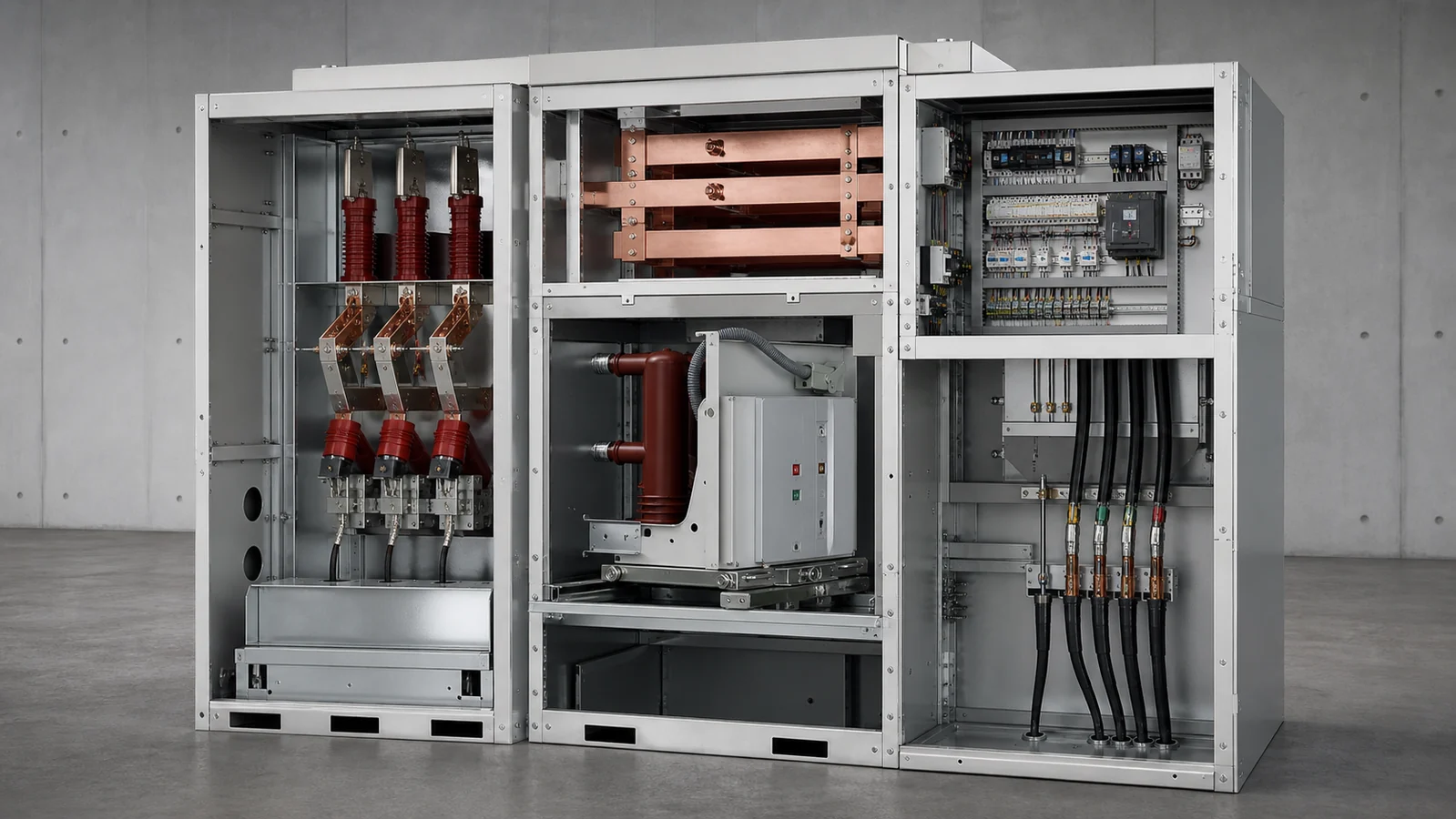
For a breakdown of the individual components that populate these compartments — CTs, VTs, surge arresters, relays, and cable connectors — the switchgear components section provides detailed specifications for each device family.
Four principal construction families address different site and network requirements. Selecting among them involves grid topology, available footprint, maintenance access, and insulation environment — not a universal ranking of one type above another.
KYN28 is a metal-clad indoor cabinet family in which the circuit breaker is commonly mounted on a draw-out truck. Metal barriers separate the busbar, breaker, and cable compartments. The draw-out mechanism can allow the breaker to be moved to a test position or fully withdrawn for maintenance while adjacent feeders remain in service, subject to the selected design and approved procedure. This construction suits primary substations and large industrial installations where individual feeder isolation and specified internal-arc performance are priorities. Confirm the applicable internal-arc classification from the selected cabinet documentation. The KYN28 metal-clad switchgear page details the available rated voltage, current, and breaking-capacity options for this family.
A ring main unit is a compact assembly designed for secondary distribution ring networks. It may combine ring-switch and protection functions in a gas-filled or solid-insulated enclosure; the module sequence and protection method vary by design. The compact footprint can suit kiosk, compact substation, or other constrained secondary-distribution installations when the selected construction and installation rating permit it. The ring main unit product range covers multiple variants. Sealed construction changes the maintenance profile, but the selected equipment still needs its specified inspections and functional checks.
XGN-series cabinets use fixed switching or protection arrangements selected for the relevant project duty. The absence of a draw-out truck can reduce cabinet depth and change the maintenance approach. The actual outage boundary, access method, compartmentalization, and protection configuration must be confirmed from the cabinet design and single-line diagram rather than inferred from the XGN family name. Fixed-type construction can fit projects where the operating and outage plan supports it and where a per-feeder draw-out arrangement is not required.
Gas-insulated switchgear uses a sealed, grounded enclosure and an insulating medium specified for the selected design. The construction can reduce the air-clearance volume relative to an equivalent air-insulated arrangement. GIS may be considered where indoor space is constrained or where the environmental and operating requirements favor the selected sealed construction. The exact insulating medium, gas-monitoring needs, pressure-relief arrangement, and maintenance requirements are model- and project-specific. GIS does not eliminate maintenance.
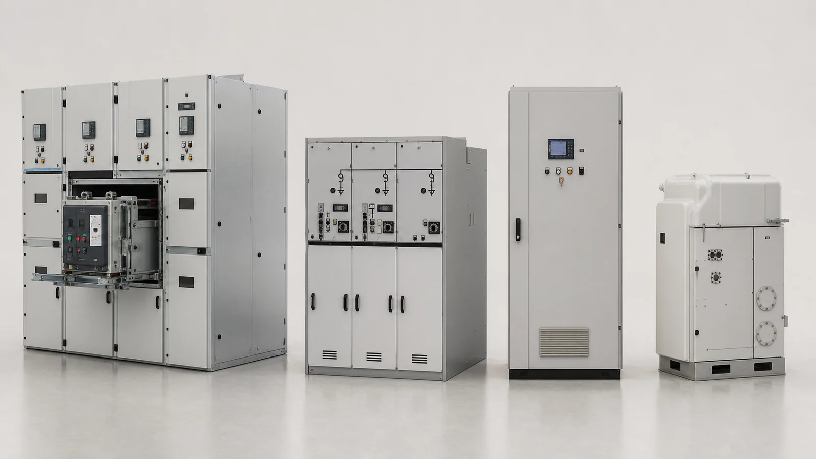
The international standard governing MV switchgear for rated voltages above 1 kV and up to 52 kV, IEC 62271-200, defines the classification criteria — metal-clad versus metal-enclosed, accessible versus non-accessible compartments, loss-of-continuity categories, and internal arc classification levels — that underpin all four families described above.
| Cabinet Family | Typical Voltage Class | Circuit Configuration | Relative Footprint | Maintenance Access Mode | Preferred Project Context |
|---|---|---|---|---|---|
| KYN28 Metal-Clad | Confirm the selected series | Commonly draw-out breaker per bay | Moderate | Design-specific test, isolation, and service positions | Primary substation or large industrial MV room |
| Ring Main Unit | Confirm the selected series | Module sequence set by network duty | Compact | Sealed-construction service plan or section outage | Distribution ring network or compact substation |
| XGN Fixed-Type | Confirm the selected series | Fixed switching or protection arrangement | Reduced depth | Design-specific outage and access plan | Industrial MV room with suitable operating plan |
| GIS | Confirm the selected series | Design-specific functional units | Compact sealed construction | Selected medium monitoring and functional checks | Constrained indoor site or project-specific environment |
All ratings are model- and project-specific. Confirm applicable values through engineering design for each installation.
The table identifies project context, not a performance ranking. A compact RMU in a ring network does not imply inferior protection to a KYN28 in a primary substation; each is optimized for its operating environment.
Before issuing a specification or entering procurement, a project team typically needs to resolve several open questions. The table below maps common uncertainties to a recommended diagnostic step.
| Symptom or open question | First test or confirmation | Likely cause | Next action |
|—|—|—|
| Voltage class not confirmed | Check transformer secondary data and utility connection information | System data is incomplete | Obtain the approved connection agreement or transformer nameplate data |
| Fault level not quantified | Check whether a short-circuit study is approved | Network study is incomplete | Obtain the project’s fault-level study before selecting interruption duty |
| Indoor or outdoor installation undecided | Check the civil layout and installation environment | Room or site design is not frozen | Confirm room dimensions, ventilation, and enclosure requirements |
| Number of feeders uncertain | Check the approved load list and single-line diagram | Bay schedule is incomplete | Complete the load schedule and ring/radial topology decision |
| Protection relay integration unclear | Check the automation architecture and control drawing | Relay interface is undefined | Confirm IEC 61850, hardwired, or project-specific relay scheme |
| Insulating-medium restrictions apply | Check applicable project and local requirements | Regulatory or owner preference is not confirmed | Verify the requirements and evaluate permitted construction alternatives |
Medium-voltage switchgear generally covers 1 kV to 52 kV, with the most common distribution classes at 12 kV and 40.5 kV. The precise boundaries vary by regional grid practice and utility definition. High-voltage transmission equipment begins above 52 kV and follows different design and testing standards. Low-voltage switchgear — below 1 kV — uses different insulation coordination and arc-fault management approaches and is classified separately under its own IEC standard series.
IEC 62271-200 distinguishes metal-clad from metal-enclosed by the degree of metal compartmentalization. Metal-clad switchgear provides grounded metal barriers between all major primary compartments — busbar, breaker, and cable — so that an internal arc in one zone cannot propagate directly to an adjacent compartment. Metal-enclosed switchgear provides a continuous outer metal enclosure but does not necessarily provide inter-compartment barriers between all primary zones. The classification affects the arc-fault consequence category and the accessibility rules for each compartment during operation.
Certain RMU and GIS designs carry ratings for outdoor installation, with appropriate IP enclosure grades and corrosion-resistant finishes. Indoor metal-clad types such as KYN28 require a weather-protected switchroom. The installation environment — temperature range, humidity, altitude, seismic zone, and pollution level — must be stated in the project specification so that the correct enclosure class and insulation coordination can be confirmed for that specific site.
In a draw-out assembly, the circuit breaker is mounted on a truck that moves between a service position, a test position, and a fully withdrawn position while adjacent feeders remain energized. This enables breaker maintenance or replacement without a section outage. A fixed breaker is bolted in place; isolating it for maintenance requires de-energizing the associated busbar section. The choice between the two affects outage philosophy, maintenance scheduling, overall cabinet depth, and per-unit cost.
A complete specification requires: rated voltage and insulation level, confirmed fault level (peak and symmetrical breaking current), rated continuous current per feeder, number and type of feeder bays, protection and control scheme including relay type and communication protocol, installation environment data (indoor or outdoor, altitude, ambient temperature, pollution category), applicable standards including any internal arc classification requirement, and any F-gas or insulating-medium restrictions. Incomplete inputs lead to under- or over-specified equipment. The RFQ input list below consolidates the minimum data set.
Submitting complete technical inputs when requesting a quotation reduces revision cycles and avoids equipment re-specification after order placement.
System data
– Nominal system voltage (kV) and rated voltage class per IEC 62271-200
– System frequency (Hz)
– Earthing arrangement (solidly earthed, resistance earthed, or isolated neutral)
– Confirmed three-phase symmetrical short-circuit current (kA rms) and peak current (kA)
– Fault duration for thermal rating (seconds)
Cabinet and feeder data
– Number of incoming, bus-tie, and outgoing feeder bays
– Rated continuous current per feeder (A)
– Cable type, voltage rating, and number of cores per feeder
– Busbar rated continuous current (A)
– Draw-out or fixed breaker preference, with justification
Protection and control
– Protection relay functional requirements (overcurrent, differential, distance, or project-specific scheme)
– Communication protocol (IEC 61850 Edition 1 or 2, Modbus, DNP3, or hardwired)
– Remote indication and SCADA interface requirements
– Metering accuracy class (energy metering, tariff, or indication only)
Installation and environment
– Indoor or outdoor installation; if indoor, substation room plan dimensions and ventilation type
– Altitude above sea level (m)
– Maximum and minimum ambient temperature (°C)
– Humidity level and pollution category per IEC 60721
– Seismic zone or required response spectrum if applicable
Project and regulatory
– Applicable national or regional standards in addition to IEC
– Internal arc classification requirement and accessibility category per IEC 62271-200
– Applicable F-gas regulations and insulating-medium preference (SF₆, fluoronitrile blend, solid insulation, or vacuum/air)
– Required design service lifetime and maintenance interval expectation
– Dimensional constraints (maximum cabinet height, depth, or total row length)



