Quotation form
Send an inquiry
Start with the basics. Our team can follow up for missing drawings, standards or packing details.
Submitted details are used only for quotation, technical review and project communication.

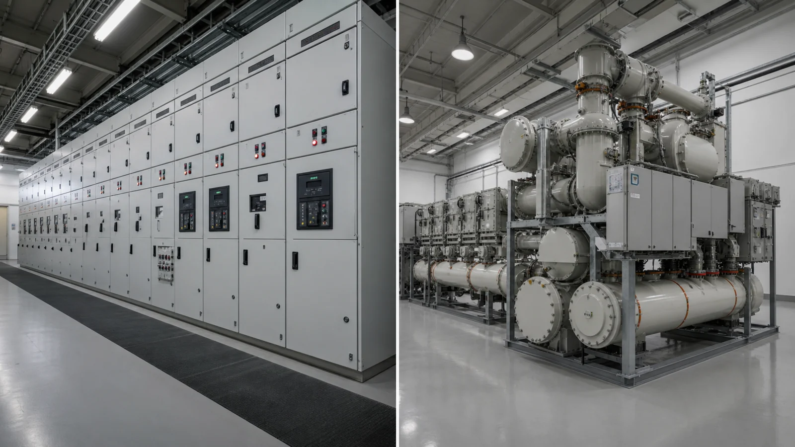
Medium-voltage switchgear selection shapes every downstream decision on your project: civil scope, building footprint, environmental compliance documentation, maintenance philosophy, and procurement lead time. Choosing between air-insulated switchgear (AIS) and gas-insulated switchgear (GIS) is therefore an architectural decision, not a product preference, and it must be resolved early enough to influence structural drawings, ventilation layouts, and approval packages. This article explains the core insulation-architecture differences, maps each difference to a project-planning input, and provides structured tables to help project teams frame specifications and RFQ submissions.
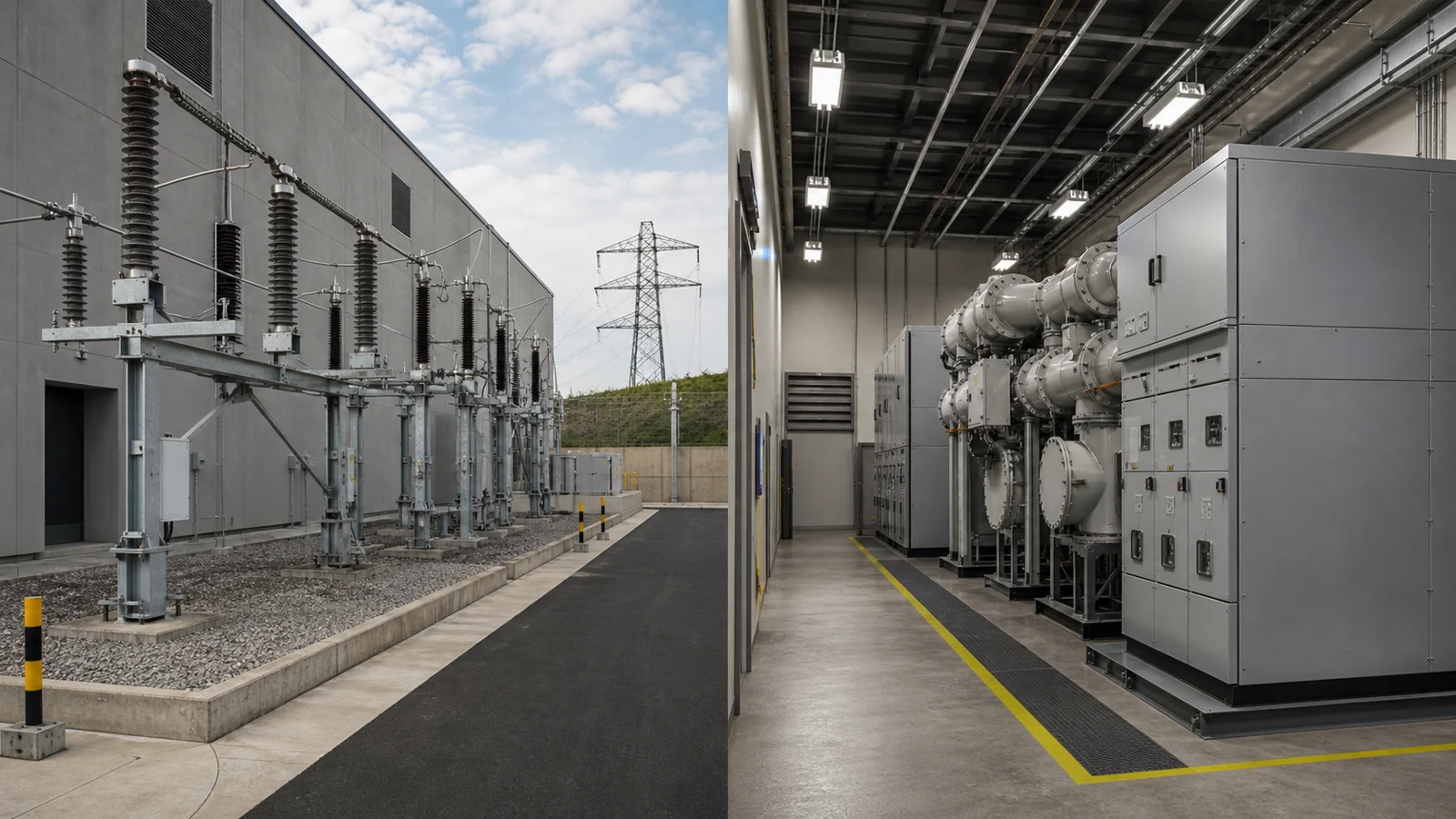
FIG-01: Conceptual side-by-side installation layout comparing a typical AIS lineup requiring open-air clearances against a GIS assembly enclosed in a sealed metallic enclosure — dimensions and ratings are project-specific and must be confirmed against OEM documentation.
Air-insulated switchgear relies on the dielectric strength of ambient air to isolate energized conductors from grounded enclosures and adjacent phases. Busbars, circuit breakers, and current-carrying components are mounted inside metal-enclosed or metal-clad cubicles that provide mechanical protection, but the primary insulating medium between live parts is the air gap itself. Applicable standard editions and categories must be confirmed through the IEC Webstore and the approved project documentation.
Gas-insulated switchgear uses an approved gas-insulation system within sealed metallic enclosures. The selected design can use different internal clearances from an ambient-air arrangement; actual enclosure, gas, dimensional, and monitoring requirements must be confirmed from the approved equipment data. The result is a factory-defined enclosure arrangement, not a generic project outcome.
Neither architecture is universally preferable. The decision boundary is determined by the intersection of available site footprint, environmental regulations in force at the installation location, local utility acceptance requirements, maintenance staffing capability, and project lifecycle targets — all of which are project-specific. A site with generous indoor floor area, straightforward ventilation, and a maintenance team experienced in switchgear access may weigh AIS favorably. A constrained urban substation, a high-altitude location, or a project in a humid coastal zone may weight differently. Establish the boundary through a structured site-condition review before issuing an RFQ.
The table below maps each technology attribute to a project-planning implication. All values described as “per specification” or “per OEM data” must be resolved against the actual product documentation supplied for the specific project.
| Attribute | Air-Insulated Switchgear (AIS) | Gas-Insulated Switchgear (GIS) | Project-Planning Implication |
|---|---|---|---|
| Primary insulating medium | Ambient air at atmospheric pressure | SF₆ or approved alternative gas, pressurized | Defines ventilation, gas monitoring, and environmental containment scope in civil brief |
| Enclosure type | Metal-enclosed or metal-clad cubicles per IEC 62271-200 | Hermetically sealed metallic enclosures | Determines building interface drawing requirements |
| Phase arrangement | Phases separated by air barriers or partitions | Phases sealed inside individual or common gas-filled enclosures | Affects busbar routing design in single-line diagrams |
| Required clearances | Governed by rated voltage and applicable standard creepage/clearance tables | Reduced by gas dielectric; per OEM dimensional data | Civil engineer needs confirmed envelope drawings before structural sizing |
| Footprint and volume | Larger per unit current rating; project-specific | Generally more compact per unit rating; project-specific | Site footprint allocation must reference OEM dimensional drawings, not generic estimates |
| Environmental containment | No special gas containment; ventilation sized for heat dissipation | Gas leak detection, pressure monitoring, and recovery provisions required | Environmental compliance scope must be defined in project specification |
| Humidity sensitivity | Internal humidity management required; condensation risk varies by installation class | Hermetic sealing reduces internal humidity exposure; seals must be maintained | Building HVAC scope and switchroom classification are affected |
| Service access | Components generally accessible without gas handling; access doors, draw-out mechanisms per OEM design | Gas recovery required before opening sealed compartments | Maintenance planning and personnel qualification requirements differ significantly |
| Weight and transport | Modular shipping sections; weights per OEM data | Shipping sections per OEM; gas typically shipped separately or factory-filled | Lifting and transport planning must use project-specific shipping drawings |
| Rated voltage range | Available across medium-voltage range; project unit ratings from OEM | Available across medium- and high-voltage range; project unit ratings from OEM | Voltage-class confirmation must appear in RFQ |
| Lifecycle documentation | Inspection-based; intervals and scope per OEM manual and project specification | Gas-handling records required in addition to electrical inspection records | Asset-management system must accommodate gas record-keeping if GIS is selected |
XIYA POWER supplies both technology families. The complete switchgear cabinet range includes medium-voltage lineups suited to a range of site conditions, and the GIS gas-insulated switchgear product page provides configuration and interface data applicable to compact substation projects.
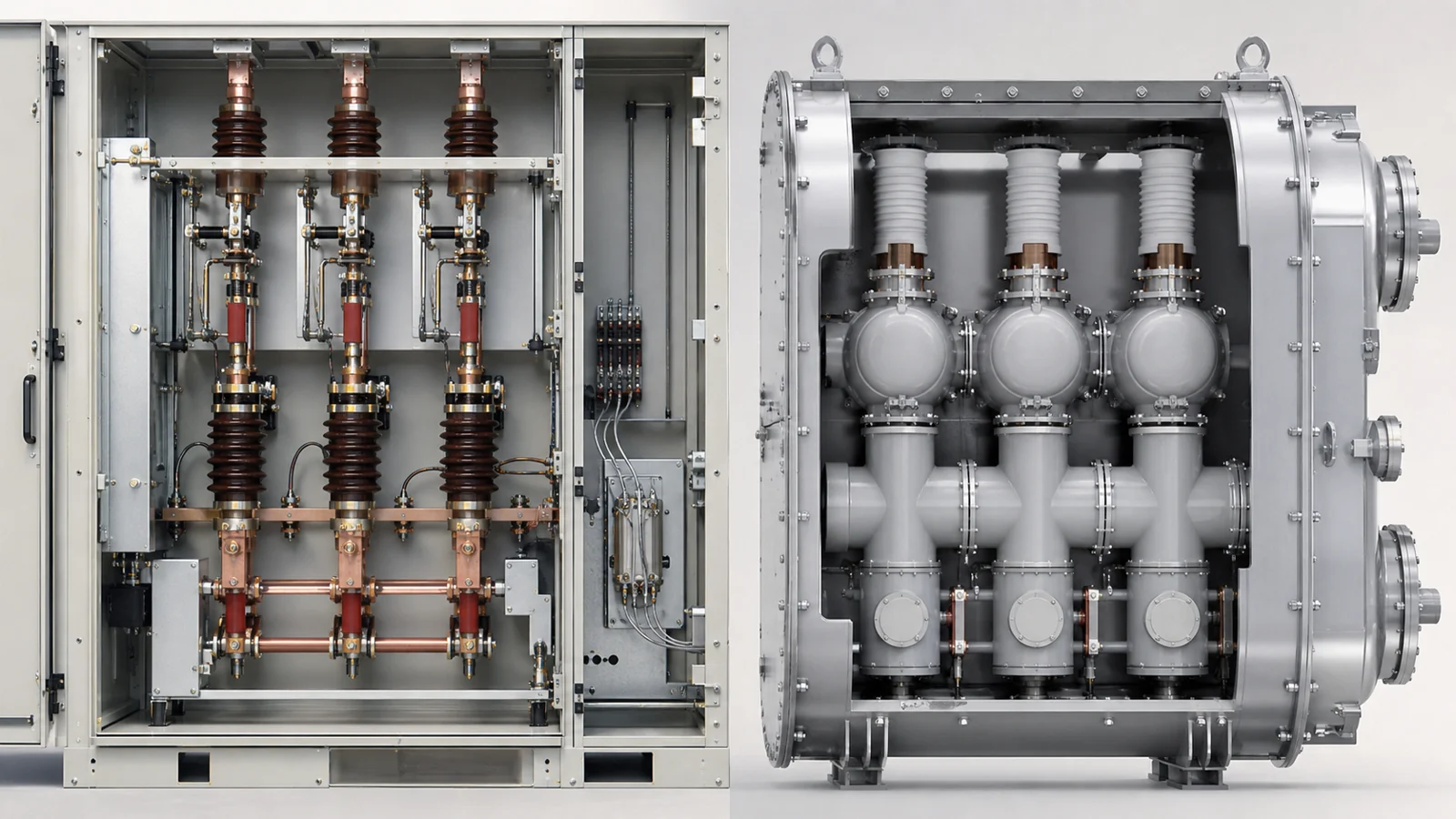
FIG-02: Schematic concept of enclosure and insulation interface layers in an AIS compartment (left) versus a sealed GIS enclosure (right) — no labels included; refer to OEM assembly drawings for confirmed component identification.
AIS installations typically require a switchroom designed around the following inputs: phase-to-phase and phase-to-earth clearances specified by the rated voltage class, forced or natural ventilation sized for heat rejection, cable entry provisions (top or bottom per OEM design), and a maintenance aisle width sufficient for draw-out operation or breaker withdrawal. Each of these inputs is driven by OEM dimensional data and the applicable IEC compartmentalization category, not by generic rules of thumb.
For GIS installations, the approved equipment data and project specification determine whether gas-monitoring signals, recovery procedures, service tools, or specific control interfaces are required. Where local regulations or the approved procedure require recovery before maintenance opening, the project specification must allocate the scope and equipment accordingly.
A complete installation documentation package for either technology typically includes:
Utility interconnection approval packages typically require confirmed rated data (voltage, current, short-circuit rating, and protection settings), single-line diagrams bearing revision control, and evidence of type testing to the applicable IEC standard. Where a local authority having jurisdiction (AHJ) requires independent witness of acceptance tests, the project specification must define the hold-point schedule before order placement. Neither AIS nor GIS obtains blanket approval by product type; approval is project- and utility-specific.
The KYN28 metal-clad switchgear and the ring main unit product pages provide configuration data relevant to distribution network projects where ring-feed arrangements or compact indoor substations are under evaluation.
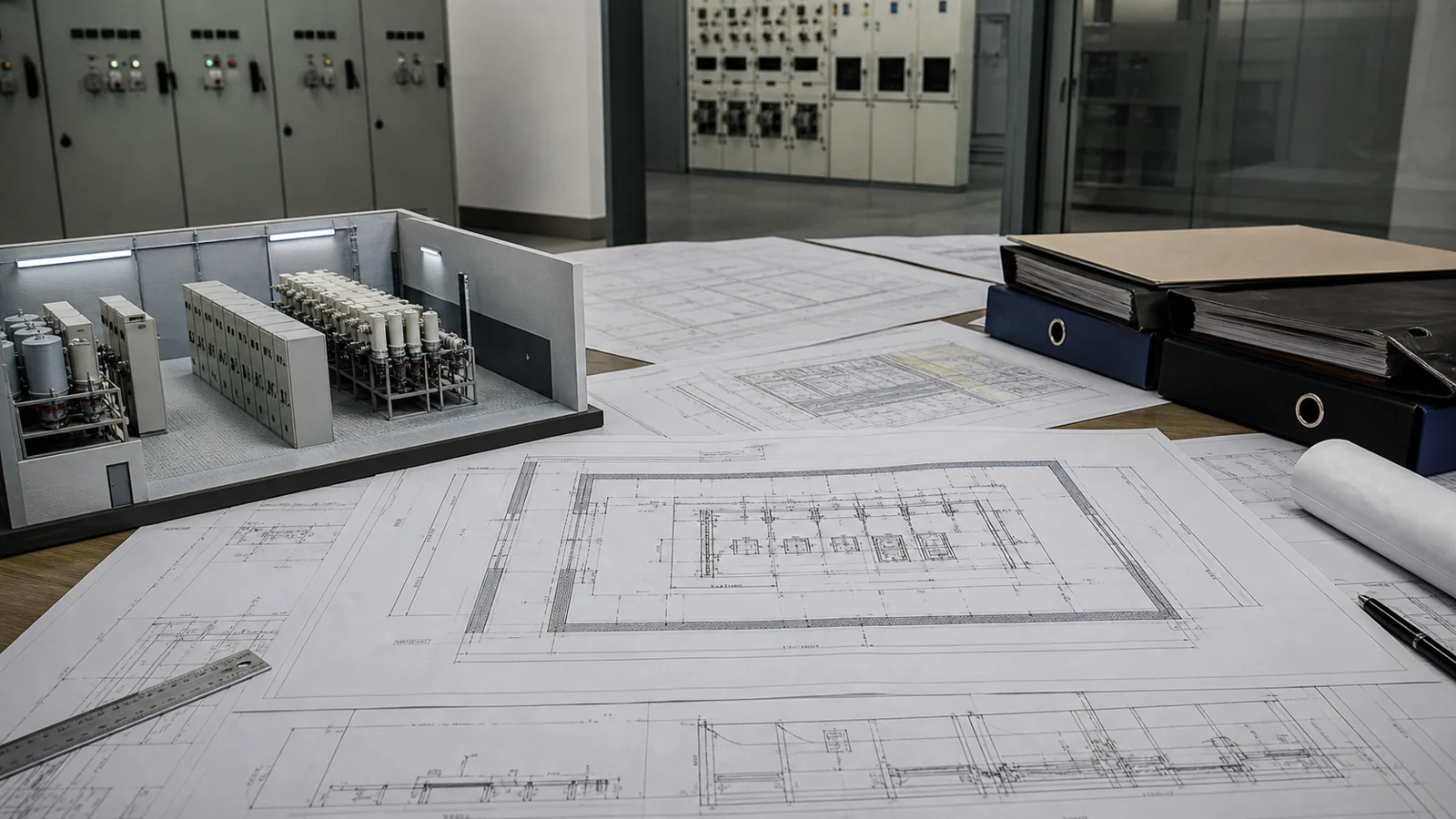
FIG-03: Conceptual review flow for project building interface and service-access planning, showing the sequence from site-condition inputs through civil brief, OEM drawing review, and maintenance philosophy confirmation — specific scope items must reflect the project specification.
The table below is explicitly illustrative. It is intended to help project teams recognize early planning gaps that may indicate AIS or GIS architectural misalignment with site conditions. It does not represent measured outcomes or documented field experience.
| Symptom | First Test | Likely Cause | Next Action |
|---|---|---|---|
| Switchroom floor area appears insufficient for AIS lineup width | Compare OEM dimensional drawing against structural floor plan | Clearance requirements exceed available footprint | Evaluate GIS compact arrangement or re-examine room layout with civil engineer |
| Environmental authority queries gas containment obligations | Request applicable local regulation reference | GIS gas management scope not addressed in project specification | Add gas monitoring, recovery, and leak detection requirements to specification before RFQ |
| Utility single-line diagram shows ring-feed connection that conflicts with proposed linear AIS layout | Review OEM ring main unit configuration options | Topology mismatch between network design and switchgear architecture | Engage OEM early to confirm ring main unit compatibility with protection scheme |
| Maintenance team reports no SF₆ handling equipment or qualified personnel on site | Assess OEM maintenance manual requirements for GIS | GIS lifecycle maintenance scope not aligned with available resources | Define maintenance contract scope or reconsider technology selection |
| RFQ responses show mismatched short-circuit ratings between AIS and GIS bids | Verify that short-circuit rating in RFQ is stated explicitly in kA and duration | RFQ did not specify rated short-circuit making and breaking current unambiguously | Issue clarification amendment stating required rated values before bid evaluation |
Complete the following inputs before issuing an RFQ. Incomplete inputs will generate non-comparable bids and delay technical approval.
| RFQ Input Parameter | AIS Requirement Notes | GIS Requirement Notes | Source |
|---|---|---|---|
| Rated maximum voltage (kV) | Confirm voltage class for selected IEC standard | Same; confirm gas enclosure rating | System single-line diagram |
| Rated normal current (A) | Per busbar and feeder circuit | Per busbar and feeder circuit | Load schedule |
| Rated short-circuit current (kA, duration in seconds) | Required for type test evidence | Required for type test evidence | Network fault study |
| Internal arc classification (IAC) | Per IEC 62271-200; define test class | Confirm applicable IAC category with OEM | Project safety requirement |
| Cable entry configuration | Top/bottom entry; quantity and size per cable schedule | Per OEM sealed cable box design | Cable routing drawing |
| Protection relay interface | Current transformer class, burden, and relay make/model | Same; confirm CT accessibility without gas release | Protection specification |
| Gas monitoring integration (GIS only) | Not applicable | Alarm, lockout contacts, and wiring termination points | Project control specification |
| Environmental containment (GIS only) | Not applicable | Gas recovery provision, drip tray if required by AHJ | Environmental specification |
| Factory acceptance test hold points | Define witness and non-witness tests | Same; add gas fill and leak test hold points | Project QA plan |
| Shipping and lifting data | Request shipping section weights and dimensions | Same; confirm gas shipped separately or factory-filled | Logistics and lifting plan |
Acceptance criteria for any switchgear assembly must be drawn exclusively from the four primary sources applicable to the project: the project specification as issued and amended at contract, the OEM operation and maintenance manual supplied with the equipment, the insulation data and gas-handling data (where applicable) provided in the OEM technical documentation package, and the test records produced during factory acceptance testing and, where required, site commissioning verification. No acceptance criterion should be derived from generic industry estimates, marketing materials, or sources not identified in the project specification.
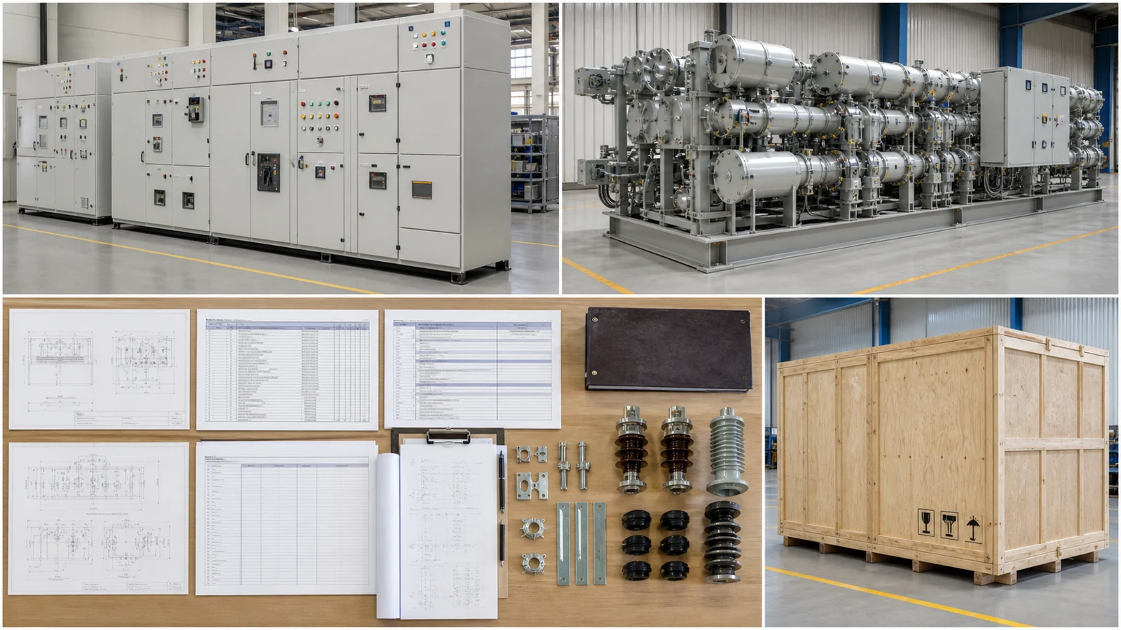
FIG-04: Conceptual structure of a buyer RFQ and technical approval package, illustrating the relationship between site-condition inputs, OEM documentation, specification requirements, and authority submission — specific content must reflect the project specification and applicable local approval requirements.
Footprint comparison is project-specific and must be based on OEM dimensional drawings for the rated voltage and current classes under consideration. Generic claims that GIS reduces footprint by a stated percentage are not reliable planning inputs. Request confirmed outline drawings from each OEM before making a space allocation decision.
Mixed configurations are technically possible in many distribution substation designs, but the interface between AIS and GIS sections requires careful attention to cable boxes, bus transition enclosures, and protection system integration. Confirm interface compatibility with the OEM before specifying a mixed arrangement, and document the interface requirements explicitly in the RFQ.
GIS maintenance procedures that involve opening sealed compartments require gas recovery before access, which in turn requires certified SF₆ (or alternative gas) handling equipment and personnel trained in its use. AIS maintenance generally does not carry this requirement, though the specific maintenance scope for either technology must be confirmed against the OEM manual supplied for the project.
Rated short-circuit making current, breaking current, and short-time withstand current are established by type testing in accordance with the applicable IEC standard. The OEM provides type test reports as part of the technical documentation package. Project specifications should explicitly state required rated values and require submission of type test evidence; these values are not interchangeable between AIS and GIS product families without OEM confirmation.
The applicable metal-enclosed-switchgear standard and project edition should be identified in the project specification and checked against the approved equipment documentation. Project specifications should reference the edition in force at contract date.