Quotation form
Send an inquiry
Start with the basics. Our team can follow up for missing drawings, standards or packing details.
Submitted details are used only for quotation, technical review and project communication.

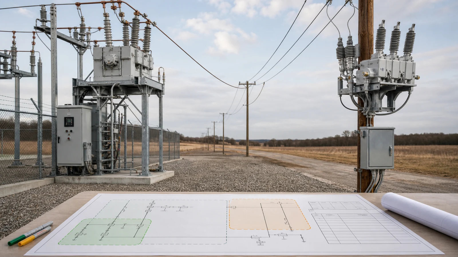
The recloser vs circuit breaker decision is about complete feeder architecture, not whether one device interrupts faults and the other does not. A recloser commonly packages an interrupter, project-defined reclosing logic, sensing, controller, records, and communication for a distribution-line position. A circuit breaker can also reclose automatically when the relay, control power, mechanism, interlocks, and station automation are designed as one scheme.
Choose by feeder position, protection-zone ownership, operating objective, duty, automation interfaces, and evidence. A source breaker plus one or more downstream reclosers can be the correct answer.
The Smart Grid equipment hub maps devices to feeder roles, while the published recloser foundation owns the basic definition. For selection, freeze the source, normal/alternate topology, protection zones, normally open points, downstream devices, restoration philosophy, and maintenance states before naming equipment.
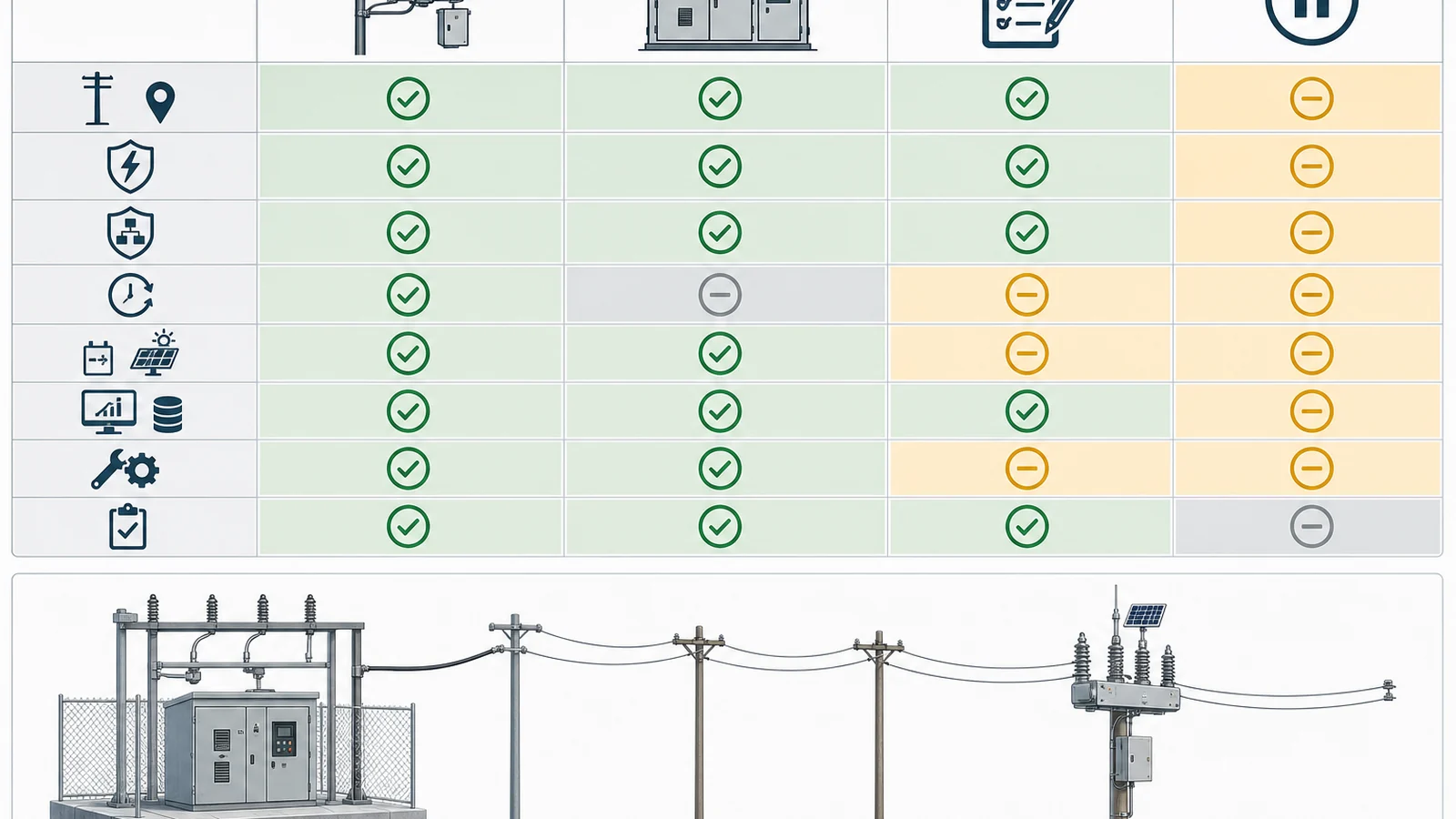
| Decision layer | Recloser-package tendency | Breaker-package tendency | Project input | Hold condition |
|---|---|---|---|---|
| Feeder position | Pole, pad, vault or line sectionalizing point | Substation, switchgear bay or station position | One-line, states and ownership boundary | Position role is only a label |
| Interruption duty | Distribution-line package within declared ratings | Broad breaker families integrated into a bay | Fault/load/grounding/switching studies | Complete duty is unresolved |
| Protection | Controller and sensors commonly packaged together | External relay, CT/VT and station scheme commonly separate | Zone map and coordination study | Settings owner is missing |
| Reclosing | Sequence commonly resident in controller | Relay/control scheme can initiate reclosing | Attempts, timing, permissives and lockout philosophy | Sequence is assumed from defaults |
| Automation | Local controller, records and communication package | Relay, bay controller, RTU/gateway and SCADA | Point list, protocol, time and cybersecurity | Interfaces are not allocated |
| Control power | Line-derived supply plus stored energy may be offered | Station DC and mechanism supply are commonly used | Energy budget and degraded behavior | Loss-of-power response is undefined |
| Installation/maintenance | Compact remote-line package tendency | Coordinated station/cubicle package tendency | Civil, isolation, access and service conditions | Site interface is not released |
| Evidence | Interrupter/controller/configuration package | Breaker/relay/control-scheme package | Applicable records and deviations | Evidence covers another configuration |
These are application tendencies, not proof of suitability. Compare the exact offered body, controller or relay, sensing, mechanism, power, software, and accessories.
Start with maximum and minimum fault current at each candidate position, grounding method, X/R basis where relevant, feeder load, cold-load and inrush behavior, switching duties, service conditions, downstream fuses/sectionalizers, upstream protection, and DER or reverse-flow conditions. Verify making, interrupting, short-time, insulation, and operating duties that apply to the complete package; do not select from nominal voltage and current alone.
The Circuit Breakers family owner shows why “circuit breaker” is not one architecture. Indoor, pole-mounted, station, SF6, vacuum, and combined-bay paths have different interfaces and evidence. A bare primary breaker does not by itself define the protection scheme; settings and logic belong to the approved relay/controller and system design.
A recloser controller may offer phase/earth overcurrent, directional, sensitive-earth-fault, voltage, frequency, cold-load, inrush, or automation functions, but none should be assumed. Confirm the exact function, sensing method, setting range, logic, firmware, and evidence. Likewise, a station relay can provide reclosing and advanced functions only when the CT/VT, DC supply, trip/close circuits, mechanism, communications, and interlocks support them.
Build one coordination chain from source protection through the candidate device to every downstream fuse, sectionalizer, relay, or boundary device. Record the curve/setting owner, study revision, minimum-fault sensitivity, maximum-fault duty, DER operating state, and the action after a coordination failure. The decision is held until the proposed device can both interrupt its duty and perform the allocated protection role.
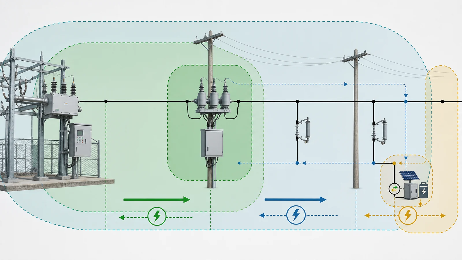
Automatic reclosing is a controlled operating philosophy, not a feature checkbox. Define the permitted number of attempts, fast/delayed elements where used, dead times, reclaim/reset behavior, final lockout, close permissives, voltage or synchronism checks where needed, and manual/remote restoration authority. No shot count or timing is universal.
In a recloser package, this logic commonly resides in the controller. In a breaker-based scheme, it can reside in a numerical relay or station controller, but the close coil, stored-energy mechanism, recharge time, anti-pumping, lockout logic, control power, interlocks, bus/feeder protection, and command authority must form one validated scheme.
Coordination intent also matters. A project may use a fast operation to avoid unnecessary fuse operation on a transient event, delayed operation to let a downstream device isolate a persistent lateral fault, or a different philosophy entirely. Cold-load pickup, transformer inrush, motor restart, feeder transfer, and DER conditions can change that choice. State the objective and model it in the coordination study instead of copying a controller default.
Lockout and restoration behavior must be explicit for both architectures. Define whether reset is local, remote, operator-confirmed, or subject to additional automation; what indications and records remain available; which permissives block a close; and how the feeder returns to normal. Do not treat “automatic” as permission to restore an uncleared permanent fault.
Compare the whole signal path. Recloser packages may use integrated CTs, Rogowski sensors, voltage sensors, external VTs, or other declared inputs. Station breakers commonly rely on separately engineered CT/VT circuits and relays. Confirm ratios, accuracy/saturation or sensor interface, zero-sequence method, secondary wiring, calibration/configuration ownership, and applicability to the protection study.
Control power deserves its own energy budget. A line device may use a dedicated voltage transformer, capacitive supply, battery, supercapacitor, or another declared arrangement. A station scheme commonly uses a battery/charger and DC distribution. For either architecture, specify energy for trip, close, controller/relay, communication, heating and accessories; charging/recovery; alarms; autonomy where required; and project-approved behavior after partial or complete loss. Avoid assuming that one power-source failure produces the same result in every design.
The scheduled feeder automation design-input guide owns topology, power, communication, data, and cybersecurity inputs. Apply those inputs here to the exact offer: point list, local/remote permissions, protocol/version, event and disturbance records if offered, time synchronization, settings/software files, user roles, audit logs, loss-of-communication state, and RTU/gateway responsibility.
Recloser and breaker schemes can both support SCADA and records. The selection issue is where those functions reside, how many integration boundaries exist, and which evidence closes each boundary.
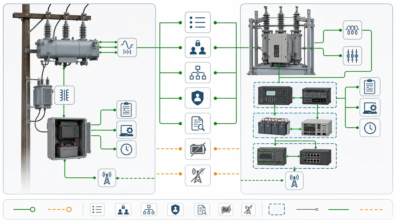
For a line recloser, coordinate pole/pad/vault structure, terminals or cable interfaces, controller cabinet, control cable, sensing/control-power source, earthing, surge-protection decision, communications/antenna, lifting, access, isolation, bypass and maintenance working space. For a station breaker, coordinate the bay or cubicle, bus/cable interfaces, CT/VT, relay panel, DC circuits, interlocks, station SCADA, earthing, access and maintenance isolation.
The Automatic Vacuum Circuit Recloser product owner shows the body/controller split and available product context. Project duty and exact offered documentation still control. The public scope of IEC 62271-111:2019 covers overhead, pad-mounted, dry-vault and submersible single- or multi-pole AC automatic circuit reclosers above 1,000 V up to and including 38 kV; it excludes devices requiring dependent manual operation. That scope does not provide this feeder’s ratings, sequence, tests, or decision.
RFQ checklist and approval data pack — shared decision inputs:
Per-offer return package:
Keep manufacturer data, the project specification, short-circuit study, coordination study, settings file and FAT record as distinct evidence sources.
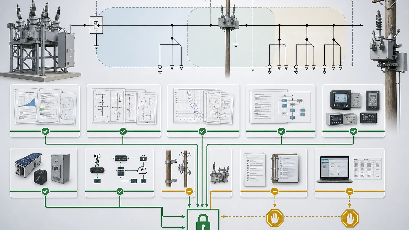
Representative engineering review, not a XIYA POWER customer, utility, field, protection-study, commissioning, outage, or service case. All values are illustrative and non-universal.
An illustrative 22 kV overhead feeder leaves a 110/22 kV zone substation, runs about 18 km, and supplies approximately 8 MVA. The three-phase fault basis is 12 kA at the source bus, 4 kA at a candidate midpoint about 9 km downstream, and 1.8 kA near the feeder end. Those values are inputs to this example only.
At the source, the proposed architecture retains a station vacuum circuit breaker with external numerical relay, station CT/VT inputs, station DC, bay interlocks and SCADA. Its complete ratings and scheme must be verified against the 12 kA source basis and required backup/protection duties. Automatic reclosing is not allocated there in this illustrative philosophy; that is a project decision, not a breaker limitation.
At the midpoint, the architecture proposes a three-phase pole-mounted vacuum recloser whose complete interrupting, making, insulation and operating duties must be verified against the 4 kA location basis and service conditions. Its controller would own the approved reclosing sequence, downstream coordination, local records and SCADA interface. The intended result is to give the downstream line zone its own interruption/restoration decision point; no operating outcome is claimed.
Decision: conditionally allocate the source breaker and midpoint recloser, but hold procurement and settings release. Close:
The same feeder could produce a different allocation if its fault duty, station architecture, DER state, restoration policy, or maintenance constraints change.
No. The interrupter functions overlap, but a recloser is normally offered as a feeder package combining the primary device with project-selected sensing, controller logic, reclosing, records and communications. A breaker-based scheme can provide equivalent functions through external relays, power, mechanisms and station automation. Compare complete scope and evidence.
Yes. The relay or controller must provide approved reclosing logic, while the breaker mechanism, trip/close circuits, control power, recharge time, anti-pumping, lockout, interlocks and permissives support the required sequence. The complete scheme must be designed and verified; the breaker label alone does not establish it.
A recloser often fits a remote distribution-line position that needs a compact interrupting, sensing, reclosing and communication package within its declared duty. A breaker package often fits a station or switchgear bay with external relays, station DC and broader bay coordination. Studies and interfaces decide, not the names.
Yes. A source breaker can own station and feeder-backup duties while downstream reclosers own separate line protection and restoration zones. Their settings, reclosing authority, lockout behavior and communications must be coordinated so simultaneous or conflicting actions do not undermine selectivity.
Use controlled load and maximum/minimum short-circuit studies, grounding data, a protection-coordination study, feeder topology/operating states, and service-condition inputs. Add DER/reverse-flow, transfer, power-quality or insulation-coordination studies where applicable. These establish duty and logic; they do not replace configuration-specific equipment evidence.
Compare complete ratings and duties, protection and reclosing functions, sensors, controller/relay, control power, mechanism, interlocks, point list, communications, software/configuration, physical interfaces, isolation/maintenance provisions, applicable evidence, tests and deviations. For a breaker scheme, include every external component required to deliver the allocated function.