Quotation form
Send an inquiry
Start with the basics. Our team can follow up for missing drawings, standards or packing details.
Submitted details are used only for quotation, technical review and project communication.

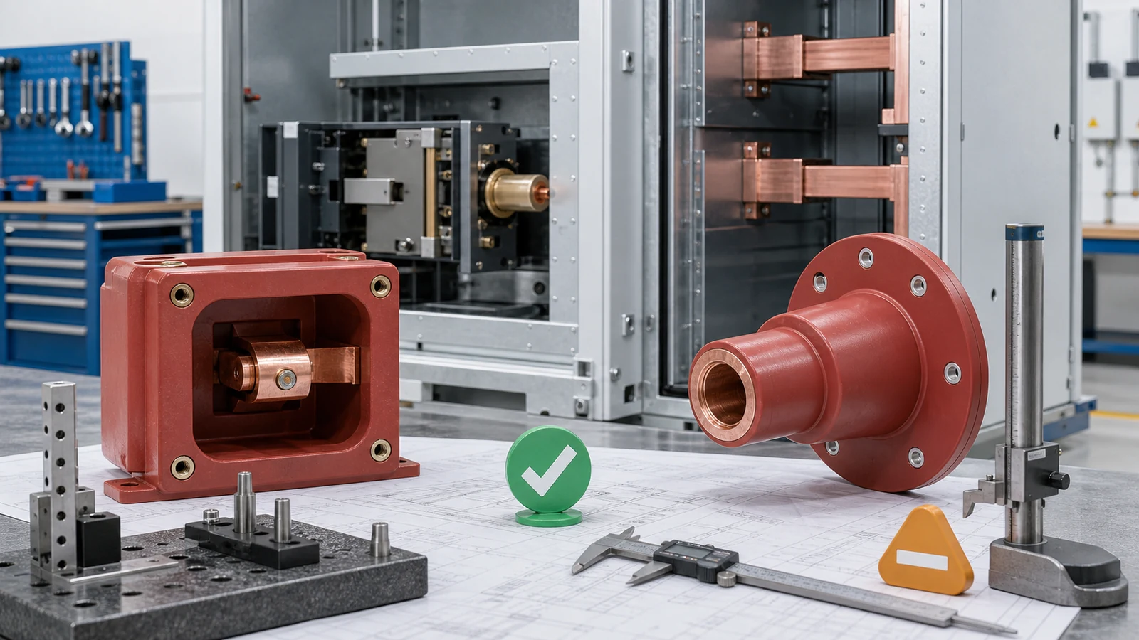
Wall bushing contact box selection is technically releasable only when the component, mating conductor or contact, cabinet datums, partition, breaker travel, insulation envelope, tolerances, drawings, and evidence describe one compatible assembly. A similar old part, matching voltage class, bore, or fixing pattern closes only part of that decision.
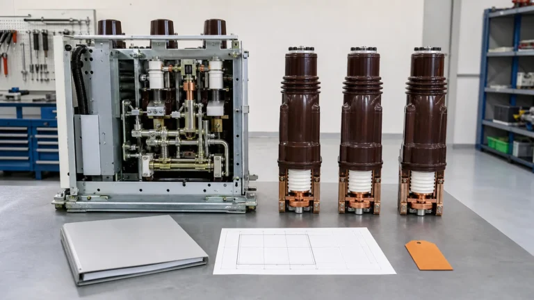
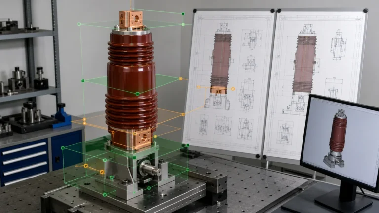
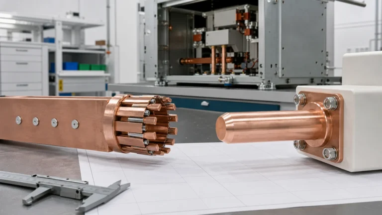
Visual disclosure: every image in this article is a generated illustrative technical visualization. It is not a XIYA POWER factory, customer, product-test, installation, commissioning, or field photograph.
The Switchgear Components pillar identifies component families. The published contact box versus wall bushing foundation owns their basic roles, cabinet positions, and common mismatch categories. Begin this selection after the family is known: open the released cabinet, breaker/current-path, partition, busbar, and insulation drawings, then build one interface-control sheet.
That sheet should connect every required input to its controlled source, supplier return, comparison method, release evidence, and approval owner. Do not let a supplier outline silently replace an assembly drawing or a used part become the master design.
| Interface layer | Controlled source | Supplier return | Comparison method | Hold condition |
|---|---|---|---|---|
| Identity and position | Cabinet BOM, assembly drawing and revision | Part identity and intended location | Revision and position match | Family or position is ambiguous |
| Electrical basis | Project specification and released assembly data | Declared applicable component data | Data-source reconciliation | Rating is inferred from shape or drawing |
| Datums | Cabinet, breaker, partition and current-path drawings | Part datum scheme and dimensions | Drawing-to-drawing map | Reference planes or centerlines are missing |
| Tolerances | Approved dimension and geometric controls | Complete toleranced drawing | Stack analysis selected by design authority | Nominals match but limits are open |
| Installed fit | Contact, shutter, conductor, insulation and service envelopes | Interface and fit evidence | Complete assembly review | One local fit hides another conflict |
| Change control | Released revisions and deviation process | Deviations and change notices | Named technical approval | Unapproved rework is needed to fit |
Use this as an RFQ checklist and controlled data pack, not as a catalogue comparison. Keep manufacturer data, the project specification, and the short-circuit study as separate evidence sources: the study can define assembly duty, but it does not establish component dimensions. A technical release requires the correct source for each decision.
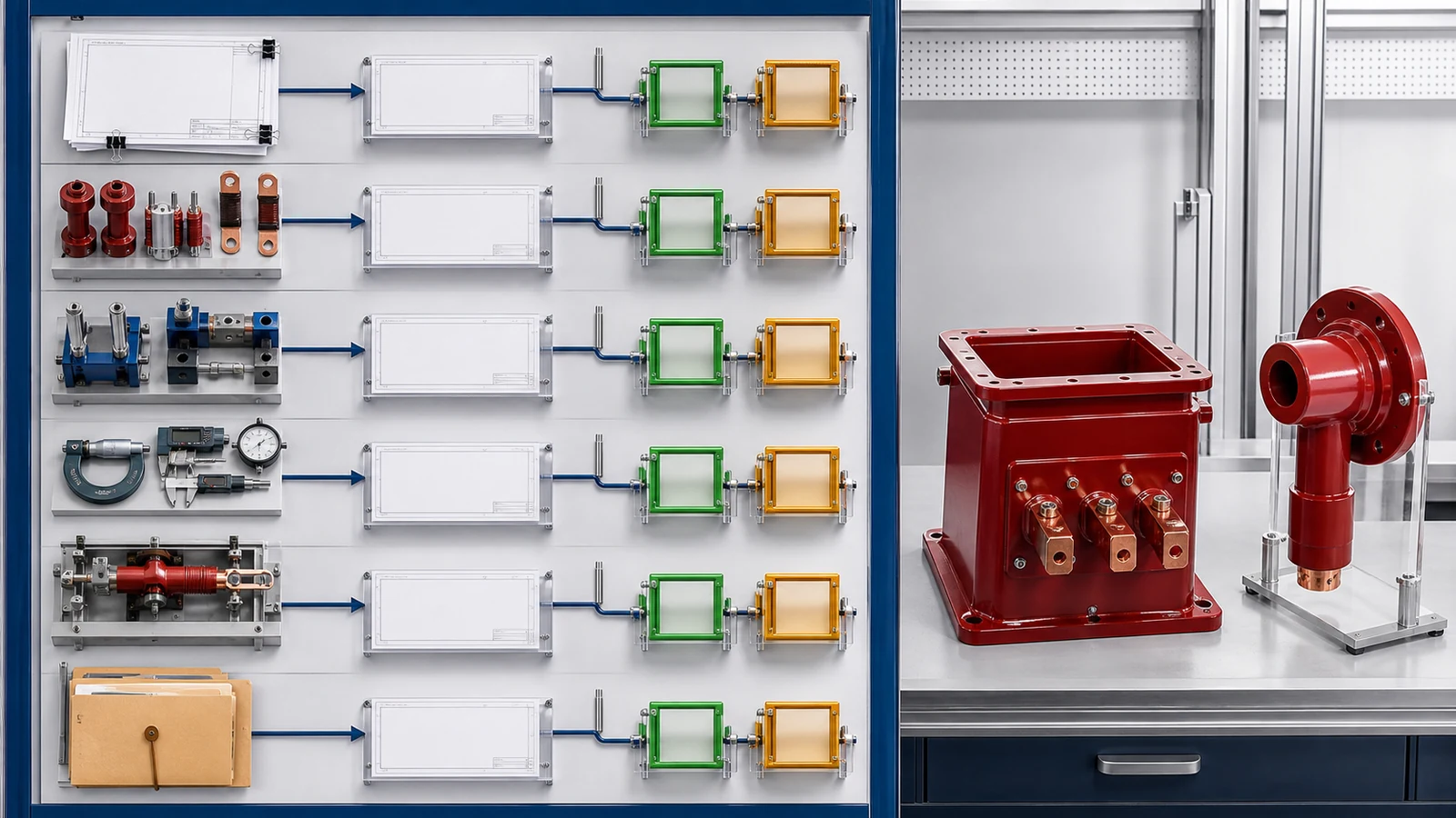
The live Contact Box page owns product navigation and entry-level drawing checks. Engineering release goes deeper by tracing a continuous datum chain from cabinet structure to the complete primary disconnect interface.
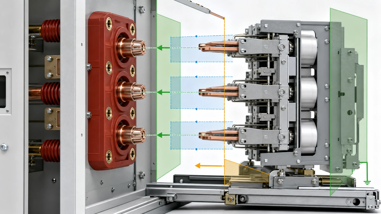
Start at the cabinet mounting plane and locating features. Map the contact-box seating face, fixing holes and orientation to the fixed-contact centerline and axial datum. Continue through the fixed conductor terminal, mating contact approach, intended engagement window, breaker truck travel and stops, shutter path, phase pitch, adjacent earthed metal, and removal route. Every link needs a controlled drawing reference.
| Contact-box interface | Cabinet-side input | Part/supplier return | Fit question |
|---|---|---|---|
| Mounting | Plane, locators, hole pattern and orientation | Seating face, holes, inserts and reference datums | Does the part locate without an unapproved change? |
| Fixed-contact position | Centerline and axial datum | Contact or conductor location from the same reference | Will the mating interface occupy its released position? |
| Breaker approach | Truck path, stops and allowed engagement window | Mouth, internal profile and fixed-member position | Does the full travel stack remain compatible? |
| Shutter and service | Shutter sweep, access and removal envelope | External body and projections | Is motion and maintenance access preserved? |
| Insulation boundary | Phase pitch and adjacent-metal envelope | Molded profile and conductor position | Does the installed arrangement remain inside the approved design? |
Matching fixing holes proves only that fasteners may enter. It does not prove contact depth, concentricity, engagement, shutter clearance, conductor terminal position, phase spacing, or removal access. Likewise, outside diameter and resin color say nothing about the internal datum chain.
Keep the neighboring contact parts within their correct ownership. Tulip geometry, finger pressure, plating, and contact-resistance acceptance require their own controlled criteria. COMP-06 checks where the complete mating interface sits in the cabinet; it does not invent acceptance values for the contact set.
The live Wall Bushing page owns model and commercial matching. For engineering release, trace the interface from the cabinet partition to conductors on both sides.
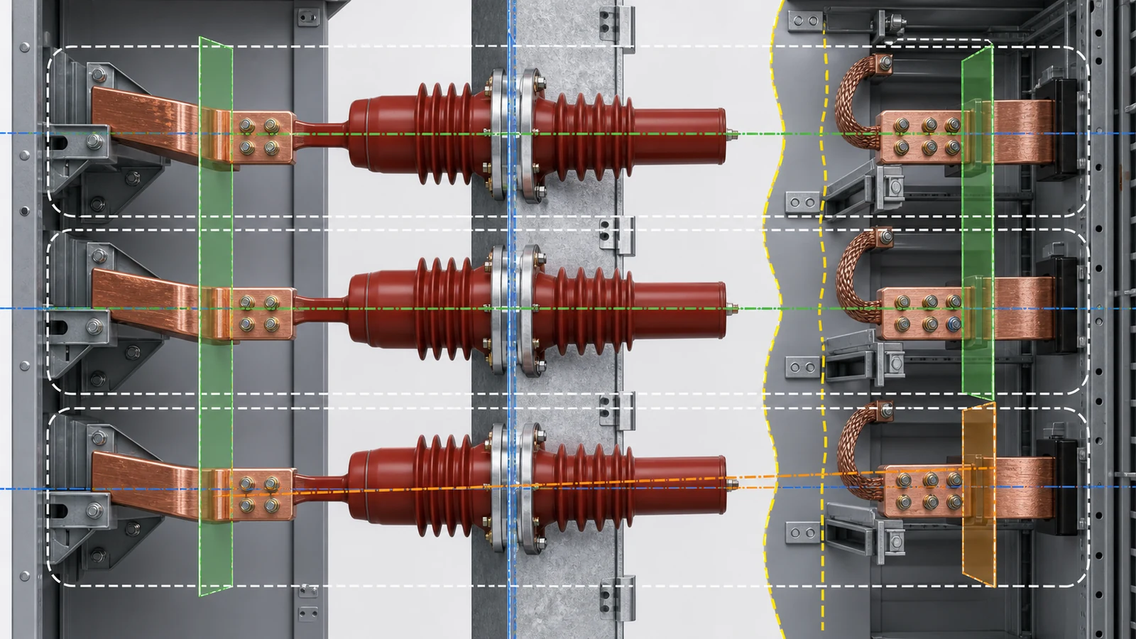
Record the partition plane, thickness, cutout, nearby folds or reinforcements, and fixing features. Map them to the bushing flange, seating face, fasteners, bore and conductor centerline. Then continue to the conductor terminal planes, phase pitch, busbar supports, flexibility or expansion provision where designed, adjacent metal, insulation envelope, access, and removal route.
| Wall-bushing interface | Controlled input | Supplier return | Release question |
|---|---|---|---|
| Partition | Plane, thickness, cutout and fixing pattern | Flange, seating face and holes | Does the bushing seat on the intended structure? |
| Conductor path | Centerline, orientation and terminal planes | Bore, conductor feature and end datums | Do both sides align without forcing the busbar? |
| Phase arrangement | Phase pitch and neighboring geometry | Installed body and conductor envelope | Is the full three-phase layout consistent? |
| Mechanical support | Loads, support points and allowed movement from the design | Declared support and connection boundary | Are forces transferred through the intended members? |
| Insulation/service | Approved surrounding envelope and access | Surface profile, projections and removal needs | Is fit shown without inferring electrical performance? |
A matching bore can coexist with a wrong conductor centerline. A matching flange can coexist with a wrong terminal plane or phase pitch. Forcing a busbar into alignment can transfer unreviewed load into the bushing, joint, support, or partition. Physical fit therefore needs the current path and structure, not only the bushing outline.
Do not turn this review into GIS sleeve selection. Gas-cabinet sleeves add sealing, conductor, and compartment records that belong to the later COMP-09 article.
Nominal dimensions are not a tolerance analysis. For each critical interface, identify the datum, nominal, tolerance type, geometric control, molded or machined surface, metal insert, coating condition, measurement method, and drawing revision. If the approved drawing requires a condition or temperature basis, preserve it rather than assuming one.
Build the stack between two functional limits. For a contact box, that may connect cabinet mounting structure, box seating and insert locations, fixed-contact position, breaker truck reference, mating contact, and stop position. For a wall bushing, it may connect partition, flange, bore, conductor feature, busbar holes, supports, and the terminal plane on the far side. The design authority decides whether worst-case or an approved statistical method is appropriate.
| Evidence source | Useful for | Limitation | Release treatment |
|---|---|---|---|
| Released assembly drawing | Design datums and interfaces | May not contain supplier manufacturing detail | Governing cabinet source |
| Supplier part drawing | Part geometry and production controls | May omit mating assembly limits | Hold omissions and map every critical datum |
| Old-part measurement | Identification and discrepancy investigation | Wear, distortion, repair, coating, access and instrument error | Supporting evidence, not automatic master |
| First-article or controlled fit record | Configuration-specific fit where required | Valid only for identified parts, revisions and method | Check applicability before approval |
| Photo or model label | Orientation and identity clues | Does not show hidden datums or tolerances | Never sufficient alone |
Measurement records need the feature, instrument, method, datum setup, result, uncertainty where required, part condition, operator or responsible function, and traceable revision. A supplier statement that two parts are equivalent is not a stack analysis. Conversely, one field measurement that differs from a drawing does not identify whether the drawing, part, measurement, or earlier modification is responsible.
The earlier switchgear component acceptance checklist owns broad incoming inspection after parts arrive. COMP-06 owns the pre-order engineering release that should prevent a known interface mismatch from reaching receiving inspection.
The official page for IEC 62271-200:2021 places prefabricated AC metal-enclosed switchgear above 1 kV through 52 kV within its public scope and summarizes assembly topics including partitions, compartments, LSC, internal-arc testing, and earthing circuits. It does not provide universal contact-box or wall-bushing dimensions. The adopted project standard and released assembly design remain the acceptance basis.
Require controlled cabinet, partition, breaker, current-path, and insulation drawings; the supplier part drawing; interface-control sheet; electrical-data source; material and traceability declarations where required; measurement plan; first-article or controlled fit evidence where specified; deviation register; change notices; and named approvals. Mark each item as supplied, applicable to the exact configuration, reviewed, or approved. Those states are not interchangeable.
| Release gate | Required evidence | Hold trigger |
|---|---|---|
| Revision gate | Current cabinet and supplier drawings | Mixed, missing or superseded revision |
| Datum gate | Complete reference-plane and centerline map | A critical dimension has no common datum |
| Stack gate | Approved tolerance/fit analysis | Nominals match but limits are unresolved |
| Assembly gate | Contact, shutter, conductor, insulation and service envelopes | Local fit conflicts with the complete cabinet |
| Evidence gate | Applicable fit/first-article and traceability records where specified | Record does not identify configuration or method |
| Deviation gate | Resolved deviation and change-control record | Drilling, slotting, grinding, shimming or bending is proposed informally |
Never use energization as a fit trial. Any change to holes, datums, conductors, supports, insulation parts, shutters, or cabinet structure requires a controlled engineering disposition and revalidation of affected interfaces.
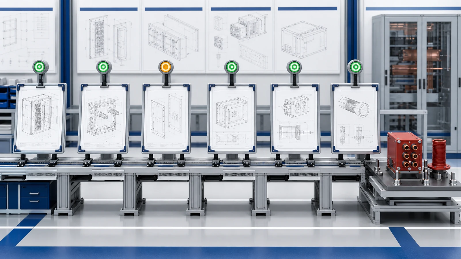
Representative engineering review, not a XIYA POWER customer, factory, inspection, test, FAT, installation, commissioning, maintenance, or field case. All quantities and dimensions are illustrative and non-universal.
The review concerns one 12 kV drawout cabinet refurbishment with six contact boxes and three wall bushings. Released cabinet assembly drawing revision C states a 210 mm phase pitch, a 245 mm cabinet-mounting-plane to fixed-contact axial datum, a 140 x 180 mm four-hole contact-box pattern, a 3 mm partition, a 110 mm wall-bushing cutout, and a 160 mm square flange-hole pattern.
The supplier contact-box drawing matches the four-hole pattern but returns a 251 mm fixed-contact datum. A used old part measures approximately 247 mm, yet the record has no measurement method, uncertainty, original inspection state, or deformation history. The supplier wall-bushing drawing matches the flange-hole pattern but places the bore centerline 4 mm above the released conductor datum.
Both selections remain on hold. The design authority must reconcile drawing revisions and the breaker/contact/cabinet engagement stack. The supplier and cabinet engineer must close shutter and insulation envelopes, while the busbar and partition interfaces need a complete fit review. Configuration-identified first-article or controlled fit evidence, deviations, and named approvals must close where the project requires them.
This example does not add current or short-circuit ratings, material grade, torque, clearance or creepage limits, test results, customer identity, site, supplier identity, modification, approval, installation, or final disposition. Matching holes in both offers do not override the unresolved functional datums.
Use current cabinet, breaker/current-path, partition, busbar, and insulation drawings; part identity and revisions; electrical data; mounting and functional datums; nominal and tolerance controls; conductor or contact interfaces; phase and adjacent-metal envelopes; supplier drawings; fit evidence where specified; deviations; and named approvals. Photos and old-part dimensions are supporting inputs only.
Not automatically. A used part may reflect wear, distortion, coating variation, repair, earlier modification, access limits, or measurement error. Compare it with released drawings and a controlled measurement record. If sources conflict, hold the selection until the design authority resolves the configuration.
The holes do not define the fixed-contact axial datum, centerline, mouth profile, mating engagement, breaker travel, shutter path, conductor terminal, phase pitch, or insulation envelope. All of those interfaces can remain wrong while the fasteners fit.
The bore does not prove flange seating, conductor centerline, terminal planes, busbar fit, phase pitch, structural support, nearby-metal envelope, or removal access. Review the complete partition-to-conductor datum chain on both sides.
Map both drawings to common functional datums, identify every tolerance and geometric control, and calculate the complete fit stack using the method approved by the design authority. Record discrepancies as holds or formal deviations; do not average values or modify parts informally.
Require current configuration drawings, a closed interface sheet, applicable electrical data, complete supplier drawing, approved stack review, material/traceability records where required, configuration-specific fit or first-article evidence where specified, resolved deviations, change control, and named technical approval.