Quotation form
Send an inquiry
Start with the basics. Our team can follow up for missing drawings, standards or packing details.
Submitted details are used only for quotation, technical review and project communication.

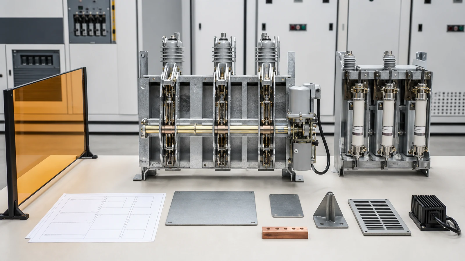
Load break switch selection is technically releasable only when the application’s current, making, breaking, withstand, fuse, environmental, control, and evidence requirements all map to the exact offered configuration. A catalogue current that exceeds normal demand closes only one line of that review.
Visual disclosure: every image in this article is a generated illustrative technical visualization. It is not a XIYA POWER factory, customer, product-test, installation, commissioning, or field photograph.
Start with the network position and required action. Record whether the device is a normally closed feeder switch, a normally open tie, a transformer branch switch, or part of a ring-main arrangement. Then define its normal state, current profile, fault-clearing owner, switching frequency, isolation boundary, and permitted operating modes.
The live Load Break Switches page owns product-family and model navigation. The Distribution Switching Equipment pillar maps load switching against isolation, fuse protection, grounding, and bypass duties. For the defining normal-load interruption boundary, use the load break switch foundation. This article begins after those choices and tests one candidate against an application duty schedule.
That schedule should state:
Do not open a catalogue comparison until each item has either a required value or an explicit hold condition.
Follow continuous current through the entire assembly rather than stopping at the switch body. Terminals, flexible connections, fuse clips, bus joints, cable lugs, and enclosure temperature can introduce a lower practical limit. The emergency case also needs a defined duration and recovery assumption: a short approved transfer is not equivalent to indefinite operation, and an unapproved emergency label is not a thermal rating. Record which study revision produced each current value so a later load-flow update cannot silently invalidate the selection.
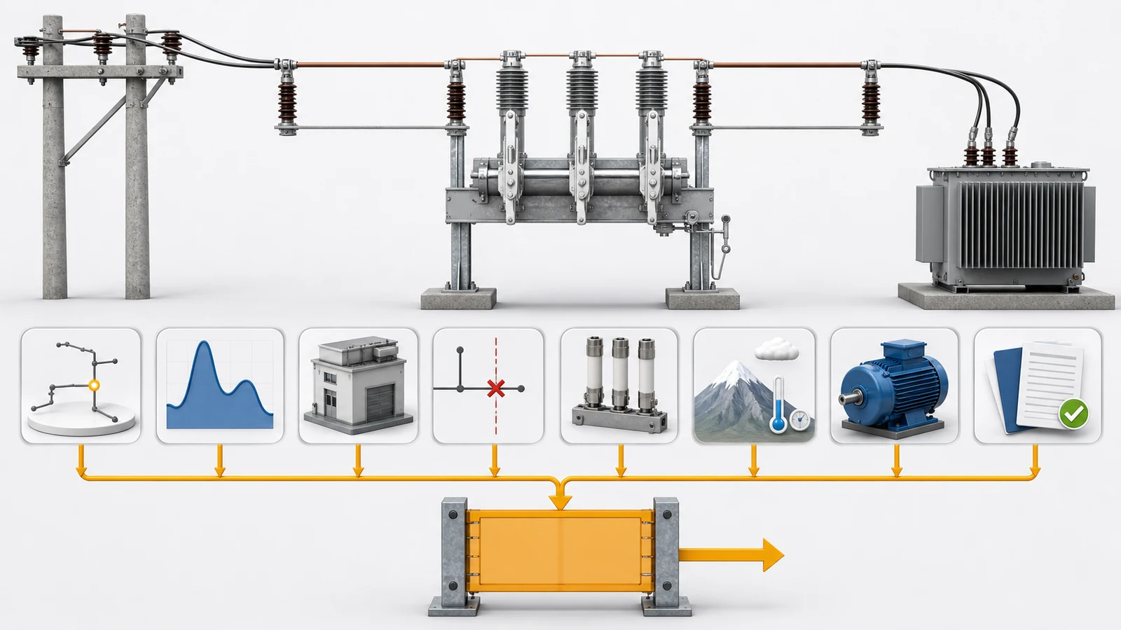
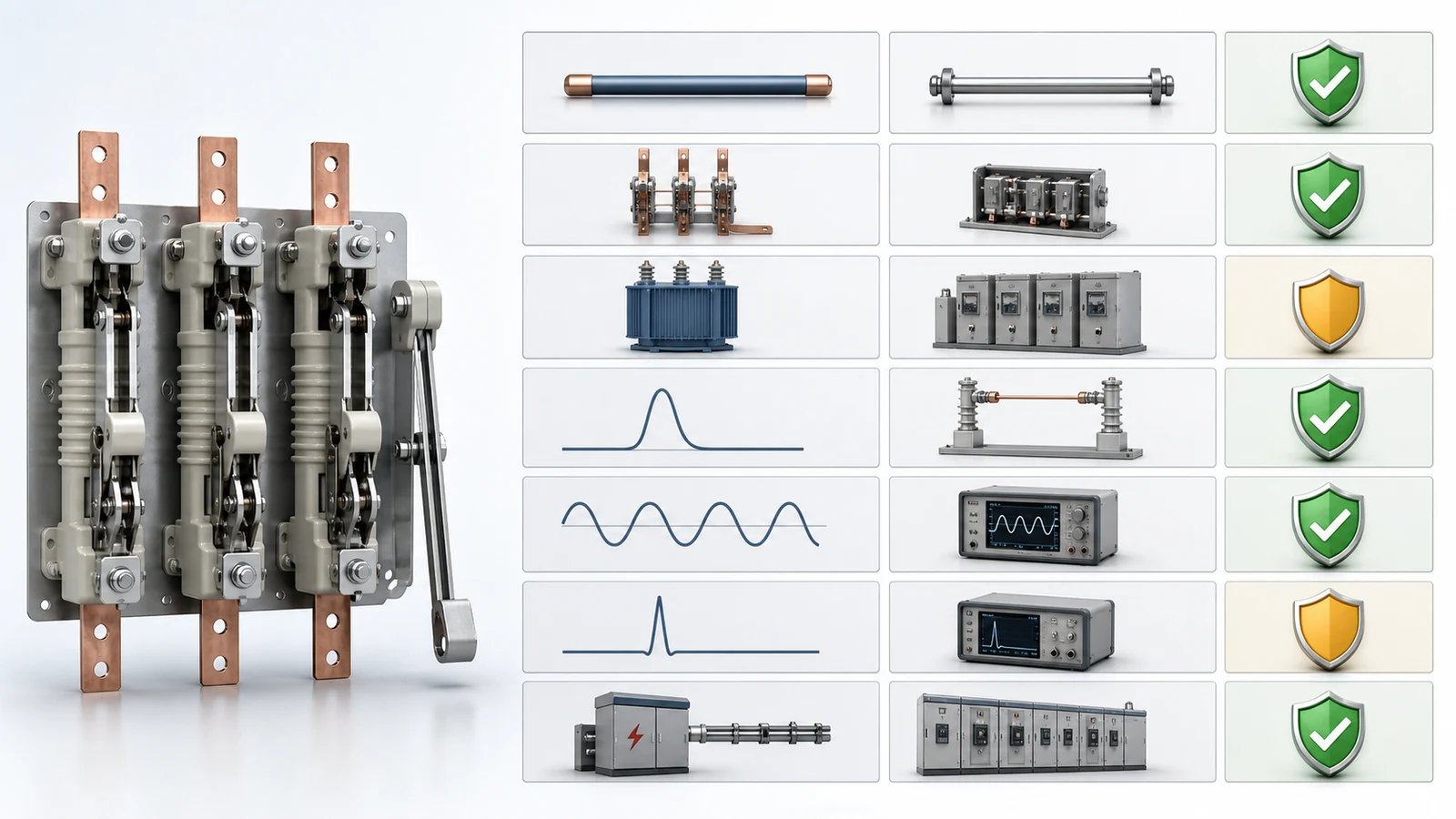
The distribution feeder equipment selection matrix owns the earlier system decision among isolation, load switching, fuse protection, fault interruption, and automatic reclosing. Once that decision points to an LBS, use this selection matrix. The official catalogue page for IEC 62271-103 establishes the standard’s public scope for switches above 1 kV up to and including 52 kV; the project must still confirm the applicable edition and candidate evidence.
| Selection axis | Required input | Candidate release evidence | Hold condition |
|---|---|---|---|
| Rated normal current | Maximum load, growth, emergency current and duration | Declared current plus applicable temperature-rise and derating basis | Actual current path or corrected capacity is unresolved |
| Mainly-active-load breaking | Current at planned opening events | Declared breaking duty for the exact configuration | Duty is absent, ambiguous, or below the requirement |
| Special-current switching | Closed-loop, cable/line charging, transformer no-load, motor or capacitor duty only when applicable | Specific declaration and configuration-applicable test basis | An applicable duty is not declared |
| Short-circuit making | Peak current at the position | Declared peak making current | Site peak and candidate value do not map |
| Short-time withstand | RMS fault current and clearing time | Declared RMS withstand value and duration | Upstream clearing time or candidate duration is unresolved |
| Peak withstand | Peak current at the position | Declared peak withstand current | Candidate value is absent or inadequate |
| Fault interruption | Named protective device and protection boundary | Express fault-interrupting evidence for that device or complete assembly | A plain LBS is being assigned unverified fault clearing |
These values are not interchangeable. Rated normal current describes carrying duty. A declared breaking value applies only to its stated current class. Making duty concerns closing with fault current present, while withstand concerns carrying fault current until another device clears it. Neither proves fault interruption, and a making rating is not permission to close onto a known fault.
Keep the short-circuit study, manufacturer data, project specification, protection basis, and operating philosophy as separate evidence sources. Technical release requires agreement among them, not the substitution of one for another.
When fuses are included, identify the complete current path through switch contacts, fuse carrier, fuse, terminals, and enclosure. The lowest applicable current or thermal limit can govern the assembly even when the switch nameplate appears adequate.
The fuse disconnect switch versus fuse cutout comparison owns the physical topology boundary. For LBS selection, record only what changes the offered switch-fuse configuration:
Component data sheets cannot prove the behavior of an unverified combination. The presence of a fuse also does not prove selectivity, eliminate a protection gap, or permit the switch to interrupt a current class outside its declaration. DSE-12 defines the interface and hold points; it does not choose a fuse rating, calculate transfer current, reproduce time-current curves, or approve coordination.
The project must also define the state after one fuse operates. Three-phase transformers, motors, converters, and other phase-sensitive loads may not be permitted to remain supplied through an incomplete phase set. A striker or common release can be part of the response, but its existence does not prove timing, all-pole opening, or the absence of a damaging interval. Those consequences belong in the approved protection and operating basis, with evidence for the complete assembly and its actual mechanical interfaces.
Voltage and current ratings are meaningful only with their service basis. Confirm nominal and highest system voltage, frequency, grounding, insulation levels, clearances, creepage, terminals, and cable or conductor interfaces for the installed arrangement.
Match the evidence to the construction. An open air-insulated switch depends directly on external clearances, insulator surface condition, and site pollution. A compact enclosed or gas/vacuum-interrupting configuration adds enclosure pressure or sealing boundaries, internal thermal behavior, cable compartments, and interfaces between insulation systems. Evidence from one mounting orientation, enclosure size, or pole spacing should not be transferred to another configuration without an applicability statement.
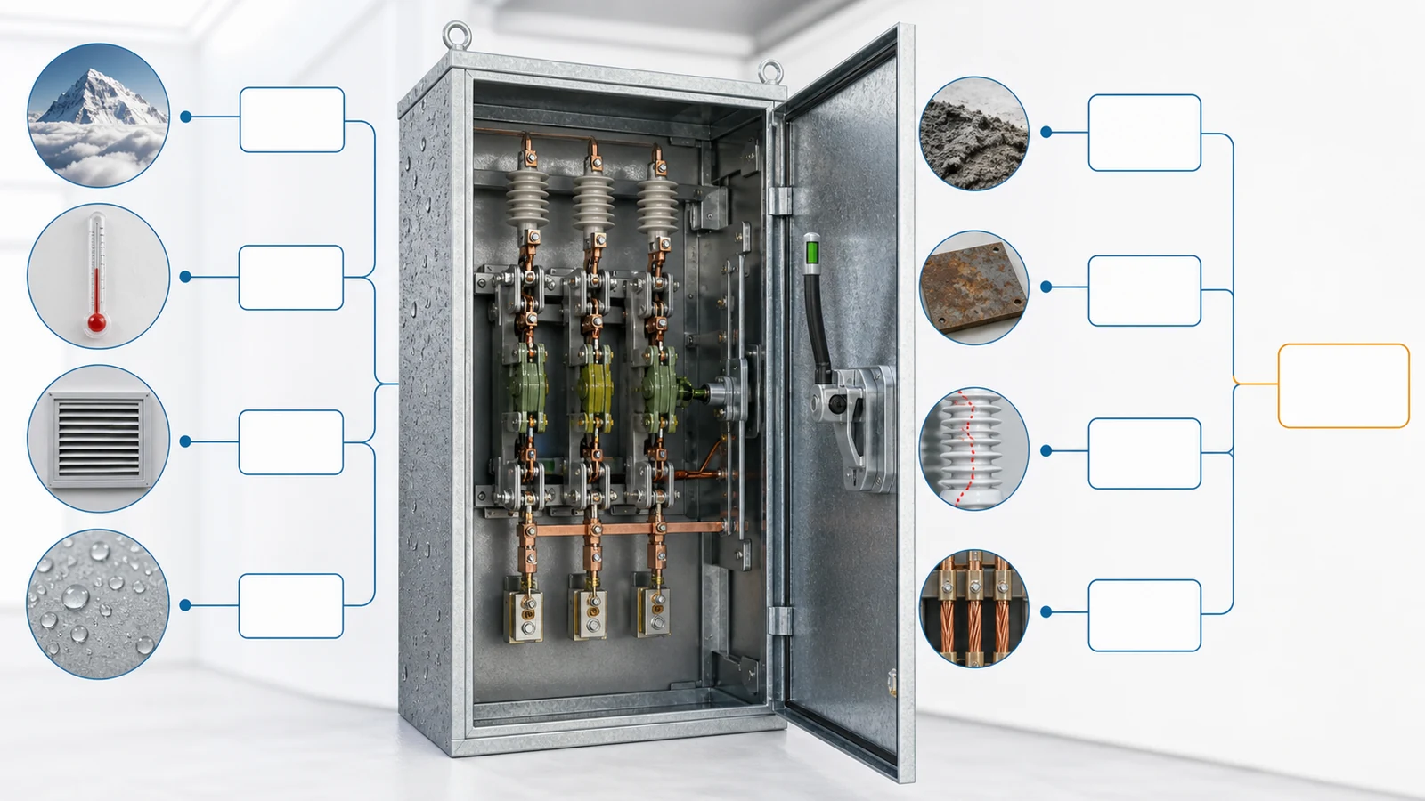
Altitude can affect air-insulation margins and cooling. Elevated ambient, enclosure ventilation, adjacent heat sources, and fuse losses can change the complete current path’s temperature-rise basis. Apply only corrections supported for the exact configuration; do not assume that a generic high-altitude or high-temperature statement preserves the catalogue current.
Humidity and condensation require an approved enclosure and anti-condensation basis. Pollution and corrosion require suitable creepage, materials, coatings, seals, and maintenance assumptions. Indoor AIS, compact metal-enclosed, outdoor air-insulated, and pole-mounted arrangements also have different mounting, access, clearances, and connection boundaries.
The release record should connect every site condition to one controlled drawing, data-sheet value, test basis, calculation, or approved deviation. If the offered interruption medium or product family changes, repeat this applicability check rather than transferring evidence from a similar model.
An application-specific RFQ checklist should identify manual or motorized operation, mechanism type, required switching frequency and endurance, control voltage and permissible band, motor demand, auxiliary contacts, local/remote states, position indication, interlocks, and behavior after control-supply loss. These are configuration inputs, not accessories to settle after ordering.
Use distinct review states for required, offered, verified, and accepted. A value copied into a compliance sheet may be offered but still lack a drawing or type-test reference. A document may be verified as authentic but still apply to a different pole spacing, mechanism, fuse carrier, enclosure, or revision. Only the accepted state closes the row, and only the named technical owner should approve a deviation from the project basis.
Map the switch to adjacent isolation, earthing, access, and protection interfaces. Obtain the interlock matrix, key-exchange logic where used, general arrangement, control schematic, terminal plan, manuals, type-test applicability statement, routine records, deviation list, and revision status. A general catalogue statement about interlocks or endurance does not close a project-specific interface.
For each requirement, name the evidence source, responsible reviewer, acceptance state, and technical hold. The final data pack should distinguish supplier capability from project permission. It must not turn an available motor drive or making rating into authority to operate, bypass, isolate, test, or energize equipment. Those decisions remain with authorized project personnel and approved procedures.
Representative engineering review only. All values and conditions below are illustrative and non-universal. This is not a XIYA POWER customer, tender, factory, test, FAT, installation, commissioning, field, maintenance, switching, fault, outage, or service case. No product compliance, installed result, or operating permission is claimed.
Consider a 24 kV equipment class on a 22 kV, 50 Hz, impedance-grounded industrial ring. The candidate position is a normally open indoor tie used to transfer one section during planned maintenance. The illustrative load record shows 360 A normal current and 520 A emergency transfer for up to four hours. The fault basis at the tie is 16 kA RMS symmetrical and 40 kA peak; an upstream breaker remains the assigned fault-clearing device.
The offered LBS is stated as 24 kV and 630 A, with a motor mechanism and 110 V DC control. Its sheet identifies mainly-active-load switching, but it does not map making, short-time withstand, peak withstand, closed-loop, cable-charging, or transformer no-load duties to the exact configuration.
Site inputs add 1,800 m altitude, +45 C maximum ambient, condensation risk, and polluted industrial air. The offered derating, insulation, creepage, enclosure, anti-condensation, and corrosion basis is incomplete. One transformer-branch option includes fuses, but the fuse family, striker/release behavior, complete-assembly evidence, and coordination approval are also missing.
Available records are the one-line, preliminary load-flow summary, fault values, candidate data sheet, general arrangement, and control schematic. Missing records are the controlled duty schedule, approved emergency-current duration, service-condition corrections, configuration-specific making/breaking/withstand evidence, applicable special-current declarations, fuse-combination evidence, interlock matrix, auxiliary-state list, endurance requirement, deviations, and named technical approval owner.
The 630 A figure exceeds both stated load values, but that observation does not close corrected continuous current, 40 kA peak making, 16 kA RMS withstand duration, special switching, fuse, control, or environmental suitability. The decision is therefore a technical hold until the complete duty-to-evidence matrix and deviations are approved.
Not by that comparison alone. Confirm maximum and emergency current, approved duration, growth, the limits of every series component, and applicable ambient, altitude, enclosure, and ventilation corrections. Then verify making, breaking, and withstand duties separately.
A plain LBS should not be assigned arbitrary short-circuit interruption. Fault clearing belongs to a fuse, breaker, or another expressly rated protective function. Making and short-time withstand ratings do not become fault-breaking ratings.
It is the declared peak current the exact configuration can make when closing under the stated short-circuit condition. Compare it with the project’s peak fault basis. It remains separate from load breaking, withstand, and fault interruption, and it does not authorize closing onto a known fault.
Consider a verified switch-fuse assembly when the switch performs declared load switching and the fuses provide the assigned protective interruption. Release still requires a complete current path, assembly evidence, striker/release behavior where used, and a separately approved coordination study.
They can change air-insulation and temperature-rise margins, depending on construction and installation. Obtain configuration-specific correction or test evidence for the actual altitude, ambient, enclosure, ventilation, and current path rather than applying an unsupported generic factor.
Provide system voltage, grounding, installation position, current profile, emergency duty, required switching duties, fault and withstand basis, fault-clearing owner, fuse interface, service conditions, mechanism/control requirements, interlocks, drawings, applicable standard edition, evidence references, deviations, and approval ownership.



