Quotation form
Send an inquiry
Start with the basics. Our team can follow up for missing drawings, standards or packing details.
Submitted details are used only for quotation, technical review and project communication.

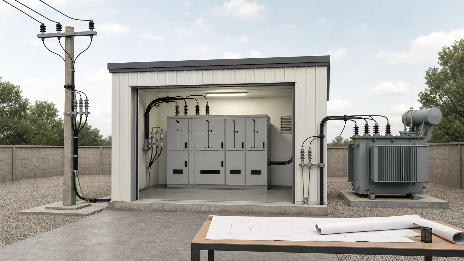
All images are generated illustrative technical visualizations, not XIYA POWER factory, product, quotation, design, installation, test, commissioning, maintenance, failure, outage, or field photographs.
Choose the surge arrester installation location from the protected terminal and the complete line-to-earth connection path. Place the selected arrester as close to that terminal as practical within the approved design. Then verify phase and earth routes, cable transitions, reflections, equipment withstand, grounding interfaces, and physical clearances. Visual proximity alone is not a release decision.
First identify the insulation boundary: a transformer bushing, cable sealing end, switchgear terminal, bus interface, pole-mounted device, or line insulator. Then trace the incoming surge path, candidate phase branch, arrester, earth return, and approved bonding point as one circuit.
The surge arrester application routes separate line and station uses from monitoring accessories. The basic surge arrester guide owns the MOV operating principle. Complete the surge arrester selection review for system voltage, grounding method, Uc or MCOV, TOV, protective characteristic, and energy duty before this placement review consumes those released inputs.
Use a location selection matrix rather than a drawing label.
| Decision | Required input | Evidence source | Release evidence | Hold condition |
|---|---|---|---|---|
| Protected boundary | Exact equipment terminal and incoming path | Single-line diagram and equipment drawing | Terminal and path match controlled revisions | Boundary is ambiguous |
| Phase connection | Route, bends, junctions, terminal load | Layout, arrester outline, manufacturer data | Actual branch is shown and mechanically compatible | Route or load is unconfirmed |
| Earth return | Arrester earth terminal, bonding point, sheath or screen interface | Grounding and bonding drawings | Direct route reaches the approved point | Return path is incomplete |
| Physical fit | Orientation, support, clearances, access, enclosure | Manufacturer data and project specification | Mounting and clearance review closes | Interface drawing is absent |
| Remote terminals | Cable length, connected equipment, reflections | Surge or insulation-coordination study | Each remote terminal is addressed | One set is assumed to protect every end |
| Technical release | Reconciled drawings, studies, deviations | Controlled data pack | Signed release evidence identifies all inputs | Any decision remains open |
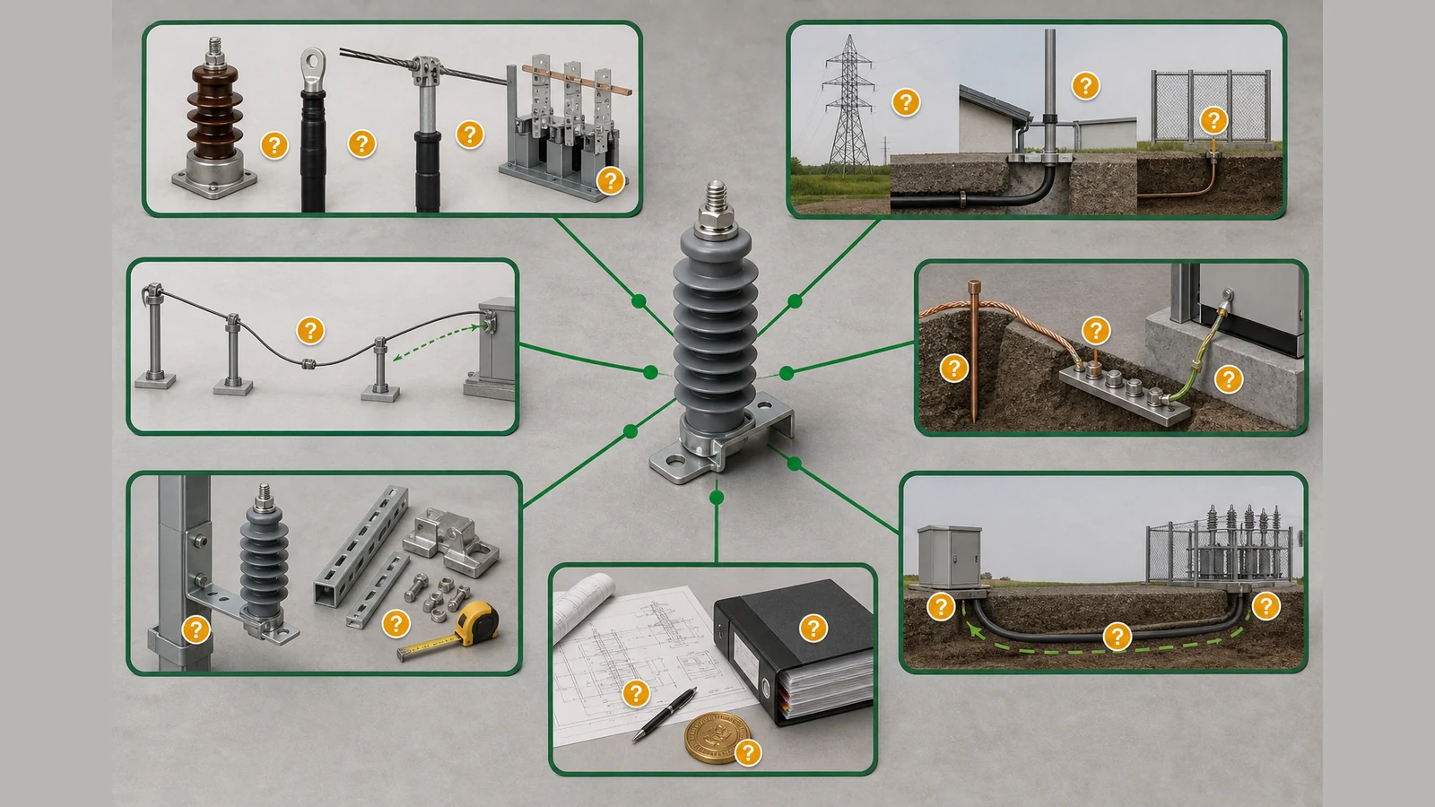
No universal lead length, cable-end rule, arrester spacing, or protection distance can replace this matrix. The relevant value is the voltage at the protected terminal under the project conditions, not the distance measured on a plan by itself.
For a transformer, review the high-voltage bushing or winding terminal that receives the incoming surge. A candidate arrester is commonly evaluated at or near that terminal, with a direct phase branch and an earth return to the approved transformer grounding interface. The project still has to confirm terminal loading, support, clearances, incoming conductor or cable geometry, and the effective stress at the winding terminal.
An arrester located at remote switchgear cannot automatically be credited to the transformer through an unreviewed cable. Cable length, connected impedances, traveling-wave behavior, reflections, equipment withstand, and the actual phase and earth paths determine whether the transformer terminal needs a separate arrester set. Another winding or network connection is also a separate protected boundary.
At an overhead-to-cable or bus-to-cable transition, review the sealing end, incoming conductor, arrester branch, earth return, and cable sheath or screen bonding as one interface. A surge can enter the cable and reach a remote termination where reflections change terminal stress. This is why one-end versus both-end protection remains a study decision rather than a universal rule.
The official IEC 60099-5:2018 page identifies selection and application recommendations for surge arresters in three-phase systems above 1 kV. Its public scope does not prescribe a universal transformer position, cable-end arrangement, lead length, or release result.
At each transformer or cable transition, require the controlled terminal drawing, cable or conductor route, sheath or bonding diagram where applicable, and arrester outline. Also require equipment withstand data, the released arrester selection, and project study output. Hold placement when the remote end is treated as protected without this evidence.
Overhead-line placement has two different jobs. Equipment protection focuses on a defined riser pole, cable termination, pole-mounted transformer, recloser, or other apparatus. The review can identify its protected terminal and direct line-to-earth connection path.
Line lightning-performance improvement distributes arresters across multiple structures. That decision requires lightning exposure, line insulation, structure grounding context, critical locations, a reliability target, and a study supporting the proposed positions. One arrester at one pole does not establish a line strategy, and a fixed pole interval is not transferable between networks.
The distribution switching equipment pillar provides the wider device context, but the line study must still separate arrester placement from switching-device selection.
| Placement objective | Protected boundary | Required return | Release question |
|---|---|---|---|
| Specific apparatus | Terminal at one structure | Terminal layout, phase and earth paths, withstand and study evidence | Is this terminal protected under the stated exposure? |
| Cable riser | Overhead-to-cable transition | Sealing-end and bonding arrangement, both cable-end conditions | Does the transition and remote end require separate protection? |
| Line performance | Selected structures along a line section | Exposure, insulation, grounding context, critical points, reliability study | Do the proposed positions meet the stated line target? |
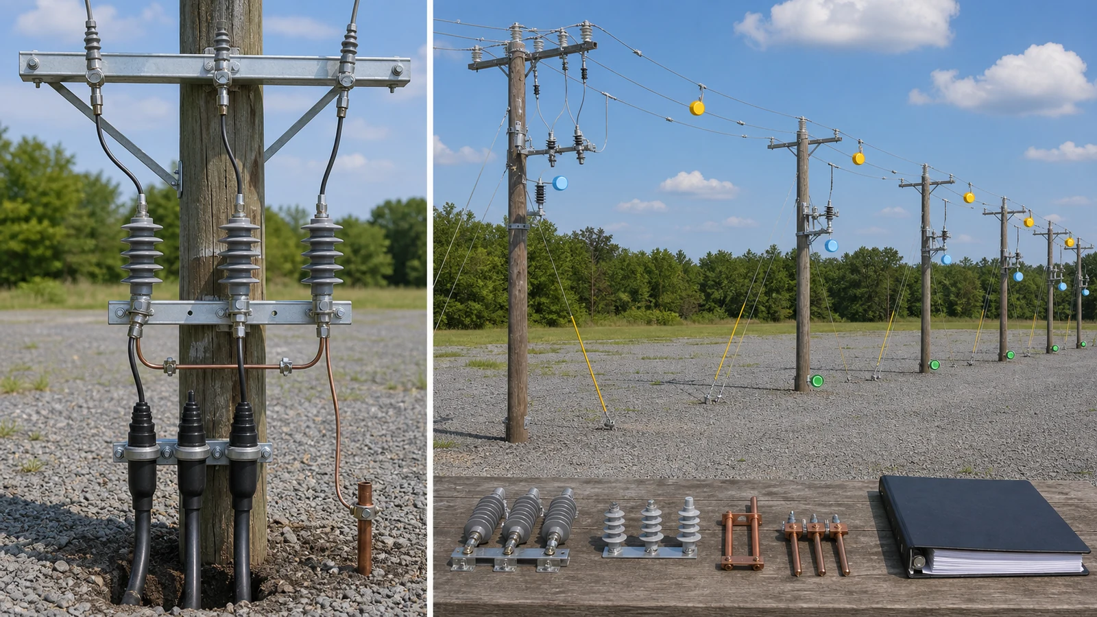
At switchgear, define whether the protected boundary is an incoming cable termination, outgoing feeder termination, bus entry, or another equipment terminal. The arrester phase branch should originate at that boundary, and the earth return should reach the approved enclosure earth bar or grounding interface without an undocumented detour.
An internal arrester compartment can control mounting and connection points, but its section drawing must show the cable termination, bus connection, phase and earth clearances, support, access, and earthing-switch interface. External mounting requires the same evidence across the enclosure boundary. A symbol inside the single-line diagram does not prove physical fit.
Use the medium-voltage switchgear cable-entry review for cable route, bend radius, termination kit, CT passage, screen or sheath path, and gland-plate coordination. This article consumes that approved interface only to position the arrester.
| Switchgear position | Phase interface | Earth interface | Placement evidence |
|---|---|---|---|
| Incoming cable | Incoming termination or connected bus | Approved enclosure earth bar | Cable-entry, bonding, compartment, and withstand review |
| Outgoing cable | Outgoing termination or connected bus | Approved enclosure earth bar | Remote-end and cable study reviewed separately |
| Internal compartment | Fixed compartment connection | Compartment earth bar | Manufacturer section, clearances, support, and access |
| External bracket | Sealing end or external conductor | Structure or enclosure grounding point | Boundary, clearances, terminal loading, and route drawings |
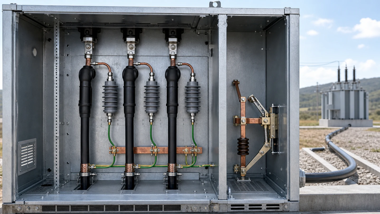
A switchgear incomer arrester does not automatically protect a transformer connected through an unreviewed feeder cable. Release the switchgear and transformer decisions separately.
The arrester protective characteristic applies at its terminals. During a fast surge, the actual phase branch and earth return can add voltage between the arrester and protected terminal. Therefore, review the complete connection loop, not only the arrester body or the shortest visible conductor.
Keep both routes short and direct as practical within the approved design, while maintaining required clearances, mechanical support, terminal loading, and access. Avoid unnecessary bends, loops, junctions, and shared paths that are absent from the study model. Do not convert this principle into a universal metre limit.
An arrester-location RFQ checklist should request:
This data pack must describe the proposed physical arrangement, not an idealized connection. Hold technical release when a route, protected terminal, remote end, bonding point, clearance, or study assumption cannot be matched to a controlled drawing.
Representative engineering review, entirely synthetic, illustrative, and non-universal. This is not a XIYA POWER customer, supplier, factory, product, quotation, design, installation, test, commissioning, maintenance, failure, outage, or field case. No placement, protection, compliance, safety, acceptance, or result is claimed.
Synthetic layout inputs: One 24 kV-class feeder has a 1.4 km overhead section ending at cable riser pole RP-01. A 220 m shielded cable connects RP-01 to an indoor metal-clad switchgear incomer. A second 35 m shielded cable connects the switchgear transformer feeder to an outdoor transformer high-voltage termination.
Synthetic candidate layout: One line-arrester set is shown at pole P-17, 65 m before RP-01, and one station-arrester set is shown in the switchgear incomer. No arrester is shown at RP-01 or the transformer terminal. The switchgear detail shows a 2.6 m phase branch from the incoming termination and a separate 1.8 m earth route to the ground bar.
The return omits the RP-01 sheath or screen bonding drawing, switchgear compartment section and clearance check, transformer terminal and grounding-interface drawing, and overhead-line lightning-performance study. It does not compare either candidate set with remote-terminal stress or document traveling-wave and reflection effects.
All distances, omissions, and hold states in the following table are synthetic.
| Synthetic placement hold | Observed return | Missing release evidence | Decision |
|---|---|---|---|
| Cable transition | P-17 set is 65 m before RP-01; no local set shown | RP-01 phase and earth routes, bonding drawing, transition and remote-end study | Hold; 65 m is an input, not a universal limit |
| Switchgear | Incomer set with 2.6 m phase and 1.8 m earth routes | Compartment clearances, cable and earthing-switch interfaces, withstand and study reconciliation | Hold; neither route is declared acceptable or excessive |
| Transformer | No local set; transformer is 35 m of cable from switchgear | Terminal geometry, grounding interface, local-option review, remote-terminal stress study | Hold; a local set is not declared universally mandatory |
| Overhead line | One set at P-17 on a 1.4 km section | Exposure, insulation, structure grounding context, critical locations, reliability target, line study | Hold; no universal spacing is inferred |
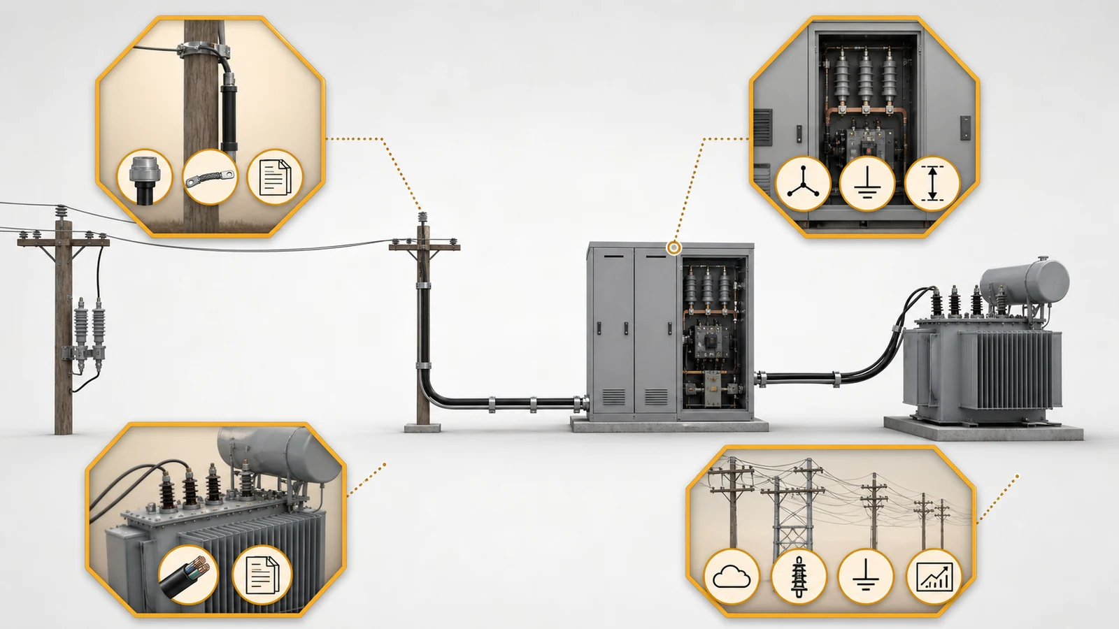
The review does not accept or reject any candidate. It shows why four distinct protected boundaries require four controlled closures.
Evaluate it at or near the protected transformer terminal, with direct phase and earth routes, then confirm terminal loading, grounding interface, incoming conductor or cable, equipment withstand, and study results. A remote arrester can be credited only when the actual connection and terminal stress are demonstrated.
There is no universal rule. Review both cable ends, cable length, sheath or screen bonding, connected equipment, reflections, withstand data, and the project study. One end may be adequate in one arrangement while another requires separate protection at the remote termination.
It limits voltage at its own connection point. Adequacy at remote equipment depends on the cable, reflections, connected terminals, phase and earth paths, equipment withstand, and study assumptions. Do not credit the remote terminal without that evidence.
Connect it to the cable or bus terminal that defines the protected boundary and to the approved earth interface. Confirm the internal compartment or external bracket, clearances, support, cable and earthing-switch interfaces, access, and the remote-end protection decision.
Keep phase and earth routes as short and direct as practical within the approved arrangement, but do not use a universal length. The acceptable geometry depends on the arrester characteristic, surge conditions, equipment withstand, connection loop, and project study.
Require controlled single-line and layout drawings, phase and earth routes, cable bonding information, and transformer or switchgear interfaces. Also require arrester manufacturer data, equipment withstand, released selection inputs, project specification, applicable studies, deviations, and a signed technical release.