Quotation form
Send an inquiry
Start with the basics. Our team can follow up for missing drawings, standards or packing details.
Submitted details are used only for quotation, technical review and project communication.

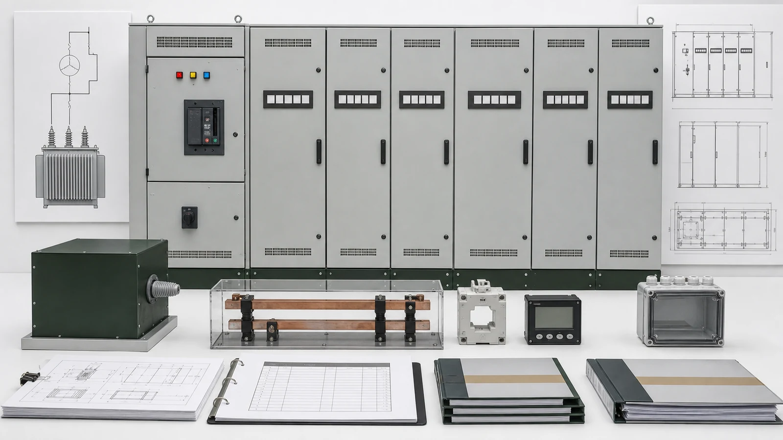
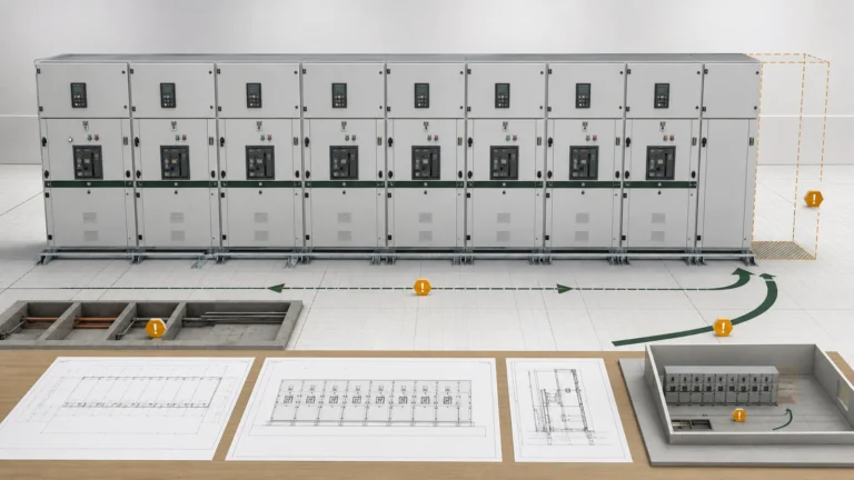
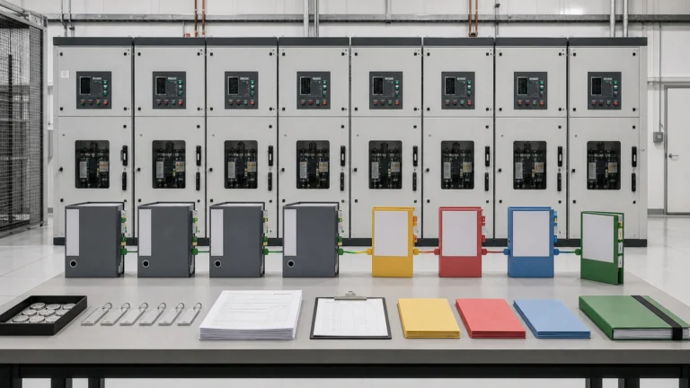
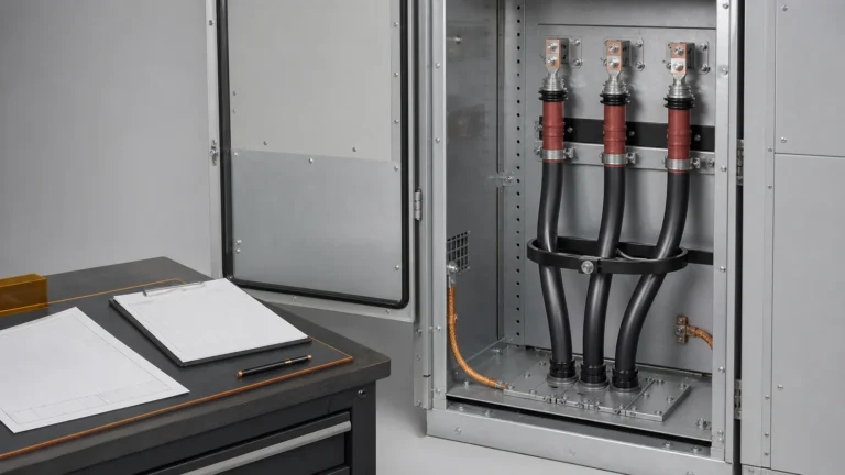
All images are generated illustrative technical visualizations, not XIYA POWER cabinets, busbars, devices, factory, test, installation, commissioning, operation, maintenance, incident, or field photographs.
By Candy Zhao, Sales Director at XIYA POWER.
A quotation-ready low voltage distribution cabinet RFQ combines one controlled single-line diagram and load/feeder schedule with explicit source, incomer, busbar, fault, feeder, metering, enclosure, interface, and evidence responsibilities. A voltage, main current, and IP degree alone cannot define a comparable assembly offer. Buyers need each technical input, supplier return, decision owner, and release hold to refer to the same configuration.
Use this selection matrix before model or construction preference turns into an unrecorded project assumption.
| Gate | Required input | Decision | Supplier return | Hold condition |
|---|---|---|---|---|
| System and incomer | SLD, source, voltage/frequency, conductors, earthing, operating states, control supply | Supply and incomer boundary | Device, source-interface and state schedule | SLD, source or responsibility differs |
| Busbar and thermal | Maximum demand, diversity, growth, ambient/altitude, neutral/PE basis | Main/distribution bus duty | Ratings and applicable temperature-rise evidence | Load or service basis is incomplete |
| Fault and protection | Prospective rms fault level, duration, peak basis, upstream device, coordination owner | Assembly, bus and device duties | Withstand, breaking/making and coordination data | Study or duty mapping is open |
| Feeders and units | Numbered loads, poles/current, device role, cable and control data, spares | Functional-unit schedule | Feeder/device/BOM return | Load, cable or unit scope is blank |
| Metering and interfaces | CT/sensor purpose, accuracy/burden, measurements, protocol, point-list owner | Metering and integration boundary | Data sheets, I/O and test interfaces | Accuracy or data boundary is unresolved |
| Enclosure and release | Environment, IP, cooling, segregation, access, dimensions, drawings and evidence | Offered configuration and release basis | GA, declarations, evidence and deviations | Any interface or evidence gate remains open |
The low-voltage distribution cabinet range supplies product-family context for fixed, plug-in and withdrawable constructions. The Complete Switchgear Cabinets pillar keeps LV, MV, RMU, fixed and gas-insulated cabinet families separate. Published range values are candidate references, not proof that one returned configuration fits a project.
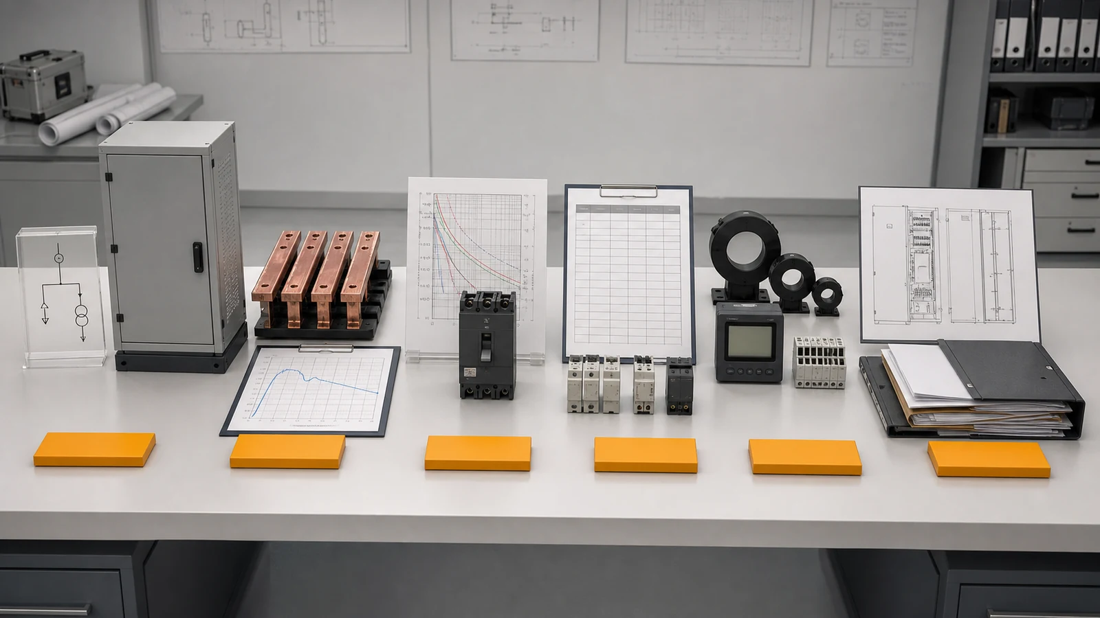
Illustrative technical visualization: exactly six amber RFQ gates remain separate, with no selected cabinet or approved offer.
Start with one SLD that identifies every normal and standby source, transformer or generator boundary, incoming connection, bus section, coupler, outgoing group, metering point and earthing arrangement. State nominal and operating voltage, frequency, phases and conductors, source data owner, and the normal and alternate operating states. If a transfer scheme is required, define its functional intent and responsibility without asking suppliers to infer it from an ATS label.
Declare the earthing system and the point at which neutral, PE or PEN responsibilities change. The RFQ should state the neutral and protective-conductor arrangement required at the assembly boundary, while the responsible engineer retains the sizing and protection basis. Harmonic content, single-phase loading and source arrangements may affect that basis; a generic percentage is not a substitute for project analysis.
For each incomer or coupler, request device type, frame and rated current, poles, breaking and making duties, trip-unit or fuse scope, interlocks, control power, local/remote authority, status points and upstream/downstream connection responsibility. Record whether cables, busduct, CTs, meters, surge protection, transfer controls, station controls and field wiring are included, excluded or supplied loose.
Projects whose functional lineup and insulation/protection scope are on the medium-voltage side belong in the medium-voltage switchgear RFQ guide. This article begins at the LV assembly boundary and does not duplicate that MV architecture.
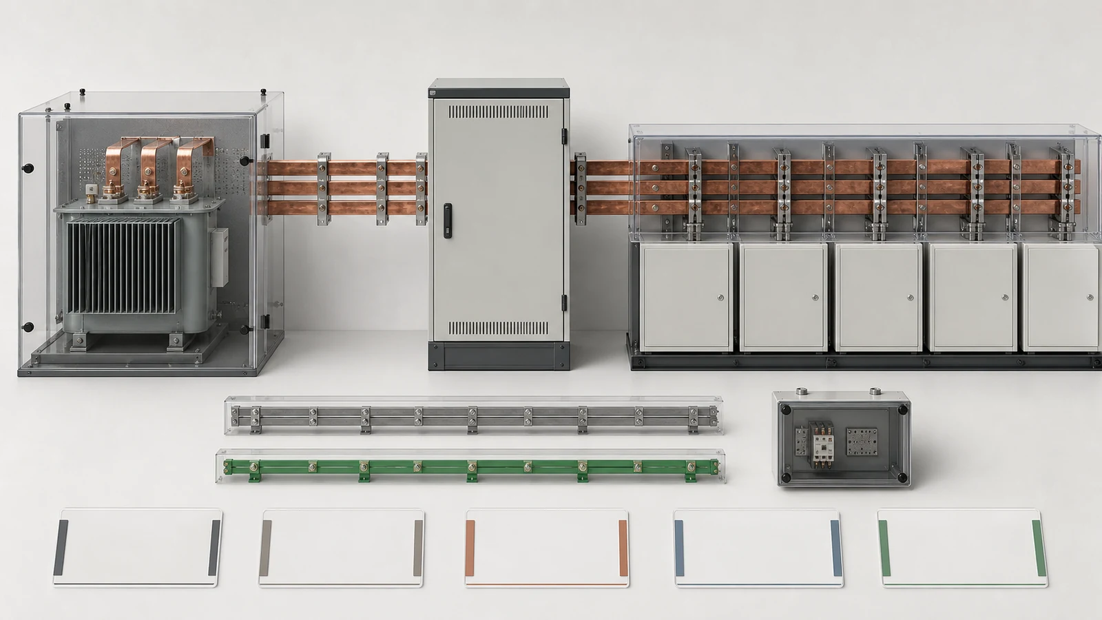
Illustrative technical visualization: source, incomer, busbar, neutral/PE and control-supply roles are shown without an energized state, operating action or accepted configuration.
Do not use the incomer frame, main-bus current and maximum demand as interchangeable values. Record the load-schedule revision, maximum demand, diversity or coincidence method, contingency state and growth allowance. Then request main-bus, distribution-bus, neutral and protective-conductor returns for the exact enclosure, cooling, ambient and altitude basis. The evidence must apply to the offered arrangement, not merely to a visually similar catalog cabinet.
The official public page for IEC 61439-2:2020 covers power switchgear and controlgear assemblies up to 1,000 V AC or 1,500 V DC and nominal supply frequencies up to 1,000 Hz, for indoor or outdoor use. Its public summary notes alignment with IEC 61439-1, internal-separation clarification, additions concerning temperature-rise verification, and consideration of IP with active cooling. It does not select project currents, fault levels, devices, segregation, IP degree or a verification route. Those decisions require the adopted standard, project specification, studies, manufacturer data and responsible technical review.
Keep the fault quantities and owners from the approved short-circuit study visible in one duty-allocation table:
| Quantity | Required input | Supplier return | Review boundary |
|---|---|---|---|
| Prospective symmetrical rms current | Approved study value at assembly and study revision | Stated comparison basis | It is a system input, not an assembly rating |
| Short-time withstand | Required rms value and duration | Assembly/bus declared duty for exact configuration | Duration and configuration must match |
| Peak withstand | Required peak basis | Declared peak withstand | Do not infer it from an unstated multiplier |
| Rated conditional short-circuit current (Icc), where used | Specified short-circuit protective device (SCPD) and basis | Declared conditional rating and SCPD dependency | It is not independent of the named SCPD |
| Breaking and making | Duty at each incomer/feeder device | Exact device capacities | Device duty is not busbar withstand |
| Coordination | Selectivity/cascading objective and study owner | Curves, data and stated responsibility | A component list does not prove coordination |
An RFQ can request these comparisons without calculating a busbar size, accepting a device, or declaring selectivity. Pending studies stay as owned holds with a due revision.
Number every outgoing circuit so the SLD, load schedule, feeder schedule, drawings, BOM and quotation refer to the same item. For each row, provide the load role, poles, normal current basis, protective-device role, fixed/plug-in/withdrawable construction, starter or drive scope, cable construction and quantity, conductor size, entry direction, terminals, control power, status/interlock points and spare designation. A spare way also needs a defined physical and electrical provision; an empty description does not establish either.
Metering requires its own responsibility schedule. Identify utility/revenue and operational functions separately. Define required measurements, CT or sensor purpose, ratios or delegated selection criteria, cores, accuracy/burden owner, meter supply and test terminals. Then state the protocol, physical interface, point-list owner, time or gateway boundary, labels and document language. Communication ready is not a testable return without these fields.
Treat enclosure and IP inputs as configuration decisions. State indoor/outdoor location, ambient range, altitude, pollution, condensation/corrosion exposure, access sides, cooling method, required segregation basis and cable-entry face. Define the required IP degree and the equipment state to which it applies. Ask how vents, fans, filters, doors, withdrawable positions and cable openings affect the declaration. IP does not by itself prove thermal performance, internal separation, maintainability or cable sealing.
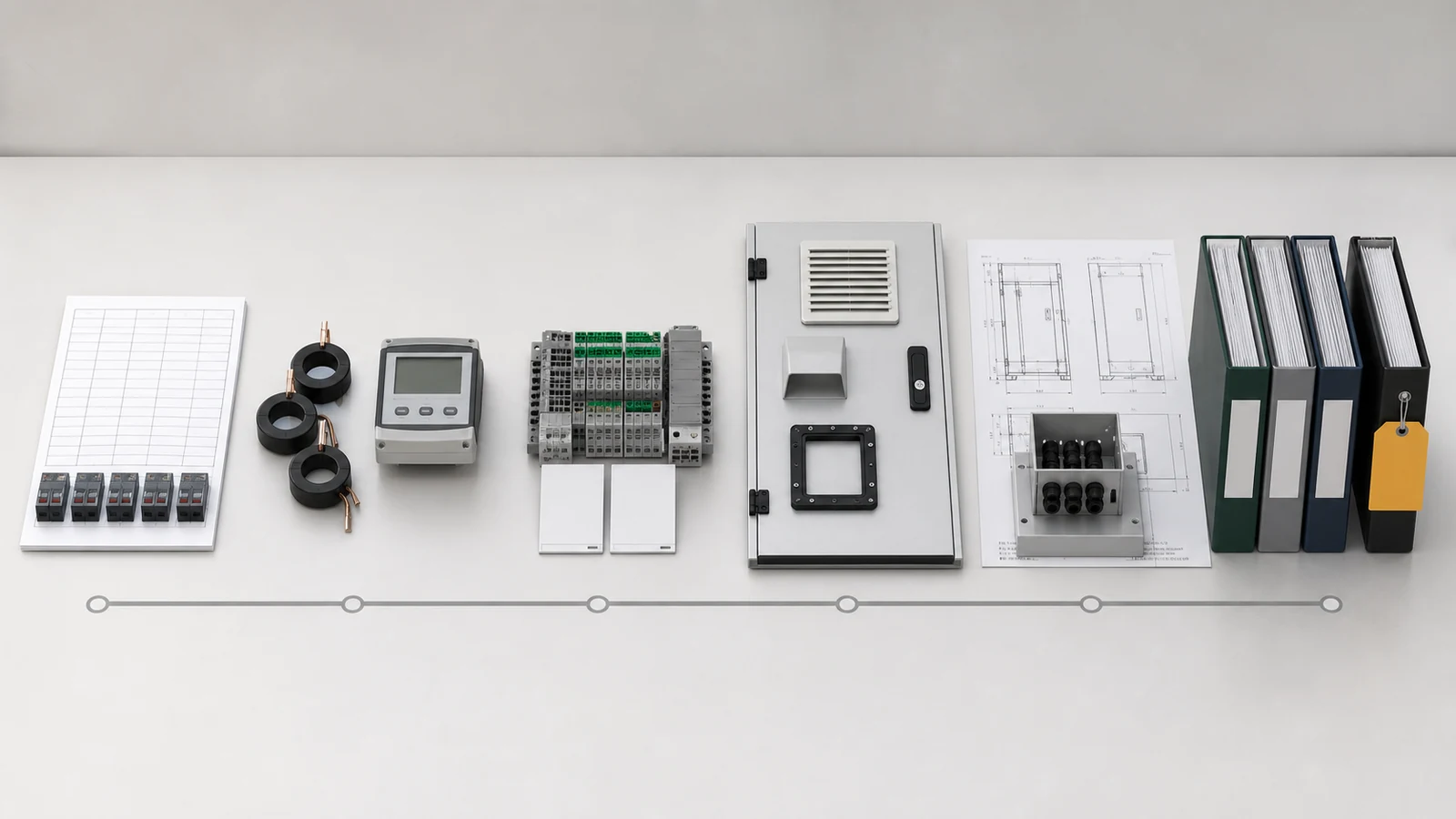
Illustrative technical visualization: feeder, metering, control, IP/environment, GA/cable and evidence records form one review chain without a pass state.
Issue an RFQ checklist that makes every bidder return the same decision package.
| Required input | Supplier return | Decision owner | Release evidence | Hold condition |
|---|---|---|---|---|
| Controlled SLD and schedules | Reconciled lineup, incomer and feeder scope | Project electrical engineer | Approved source set | Functional scope differs |
| Load and service basis | Main/distribution bus and thermal return | Design engineer | Applicable manufacturer/design-verification evidence | Configuration applicability is absent |
| Fault study and device duties | Withstand and device comparison | Protection engineer | Approved study-to-rating schedule | Study or device mapping is open |
| Metering/control requirements | CT, meter, I/O and protocol schedules | Metering/control owner | Approved interface schedule | Responsibility is unclear |
| Environment, IP and interfaces | GA, cooling, segregation and cable returns | Electrical/civil owners | Reconciled drawings and declarations | Fit or service basis is open |
| Inspection and documents | Inspection/test plan, evidence register, deviations | Quality and technical authorities | Closed records and named release | Any deviation or evidence item is open |
The return data pack should retain the stated configuration, drawings and revisions, rating schedules, component data, design-verification evidence applicable to that configuration, inspection/test plan, labels, document register, deviations and named technical release. A quotation is not that release.
Detailed room grid, dimensions, access/handling volumes, foundations, trenches and extension space remain with the switchgear GA drawing review. Send the controlled SLD, schedules and interface inputs through the XIYA POWER contact page; do not replace them with an informal list of desired ratings.
Invented representative procurement review for method demonstration only. It is not a XIYA POWER customer, supplier, quotation, order, design, type or design verification, factory, inspection, FAT, installation, commissioning, operation, maintenance, incident, or field case. Every system detail, rating, quantity, dimension, document, and returned value below is fictional and non-universal.
This representative engineering review uses one invented indoor 400 V, 50 Hz, three-phase four-wire plus PE main distribution lineup supplied from one transformer secondary. Fictional maximum demand is 1,600 A; a candidate return states a 2,000 A incomer and 2,500 A main bus. A fictional approved-study input is 42 kA symmetrical rms prospective current at the assembly. The RFQ requests review against 50 kA for 1 s and a 105 kA peak basis. None of these values or devices is accepted or declared adequate.
The fictional schedule has fourteen outgoing circuits from 63 A through 630 A and two spare functional-unit positions. A candidate metering return states one class 0.5S multifunction meter and RS-485. The candidate enclosure return states indoor IP42 with natural ventilation, while the room input states 45 C maximum ambient and restricted rear access.
| Open hold | Invented gap | Evidence required before decision |
|---|---|---|
| System and incomer | Source impedance, earthing, neutral/PE, device duties, control supply and operating state do not share one approved SLD | Reconciled SLD, source and responsibility schedule |
| Busbar and fault | Demand, candidate currents, study value, requested withstand/peak basis, conductor basis, thermal evidence and coordination are not mapped to one adopted basis | Study, specification and configuration-specific evidence |
| Feeders and metering | Cable and starting/control fields, CT ratio/burden, protocol, point list and test boundary are incomplete | Approved feeder and metering/interface schedules |
| Enclosure and evidence | IP, ventilation, ambient, access, segregation, dimensions, cable interface, verification evidence, inspection plan and deviations remain open | Reconciled drawings, applicable evidence and named release |
All four holds remain open. No product, rating, configuration, compatibility, compliance, verification, acceptance, release, commissioning result or field outcome is selected or claimed. Missing evidence records an open decision; it does not prove failure or noncompliance.
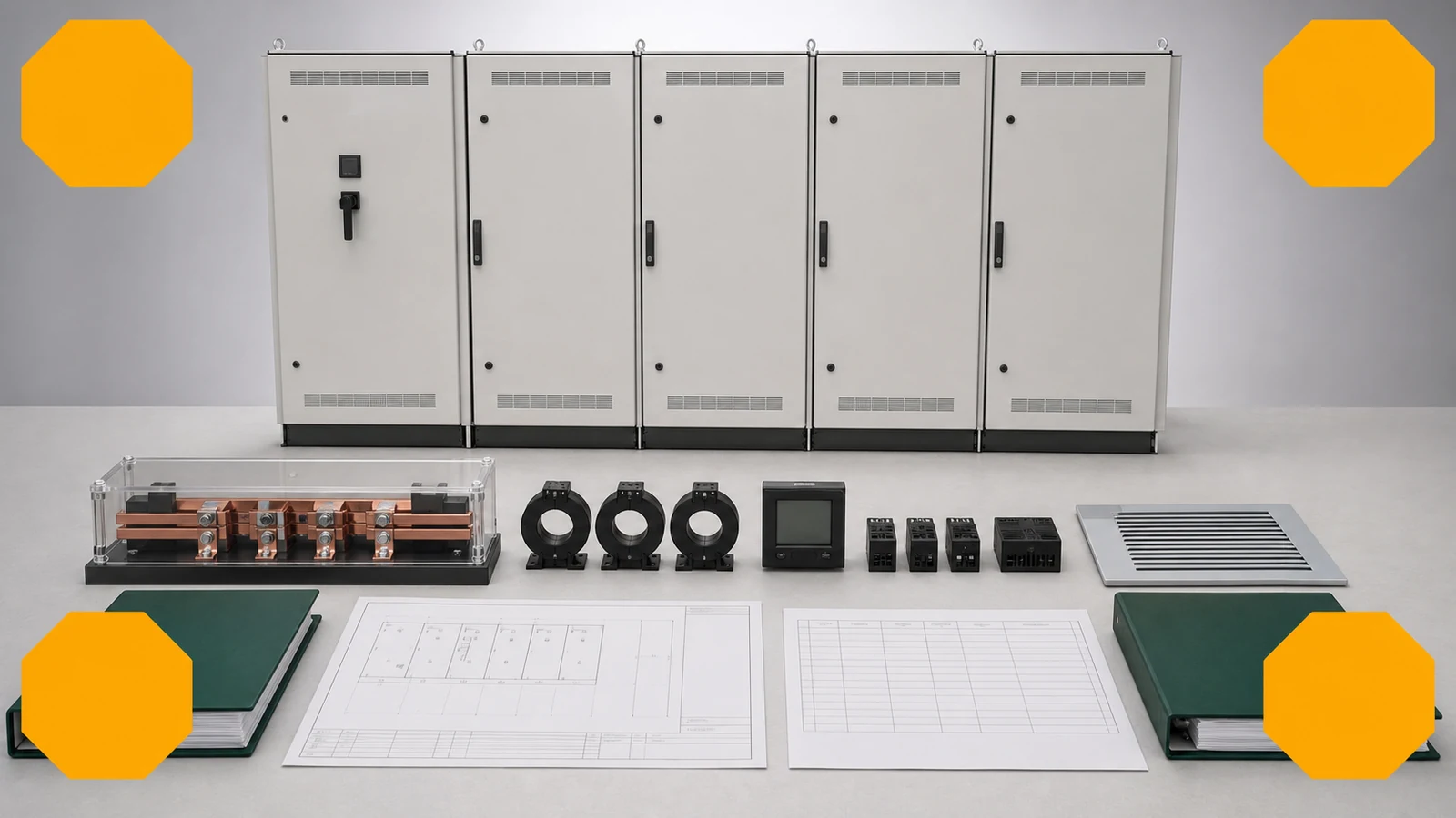
Illustrative technical visualization: one invented LV cabinet review has exactly four amber holds, with no accepted rating, verified configuration or release state.
Include a controlled SLD, numbered load/feeder schedule, source and earthing data, incomer and operating-state requirements, bus current basis, fault-study inputs, device duties, metering/control interfaces, environment and IP requirements, drawings, evidence, inspection plan, deviations and release responsibility. Each value should identify its source, revision and owner.
State maximum demand, diversity/coincidence basis, contingency state, growth, ambient and altitude, then request incomer and main/distribution bus returns separately. The incomer also needs breaking/making and protection duties; busbars need current, neutral/PE, thermal and short-circuit evidence for the offered configuration.
State the prospective symmetrical rms current at the assembly, study revision, required duration and peak basis. Where conditional rating is used, identify the upstream protective device. Request assembly/bus withstand and each device’s breaking/making capacities separately, with the coordination owner and evidence.
Use one row per numbered circuit with load role, poles, current basis, device and functional-unit type, starter/drive scope, cable quantity/construction/size/entry, terminals, control power, status/interlocks and spare designation. Blank cable, control or load fields should remain visible holds.
Separate revenue and operational metering. Define measurements, CT/sensor purpose and selection responsibility, ratio, cores, accuracy, burden, meter supply, test terminals, protocol, physical interface, point-list owner, gateway/time boundary, labels and documents. This makes the return testable instead of merely communication ready.
No. IP addresses ingress protection for a defined enclosure state; it does not establish current capacity, temperature rise, segregation, cable sealing, room fit or maintainability. Confirm the required state and faces, cooling/ventilation effect, environment, access and configuration-applicable evidence separately.