Quotation form
Send an inquiry
Start with the basics. Our team can follow up for missing drawings, standards or packing details.
Submitted details are used only for quotation, technical review and project communication.

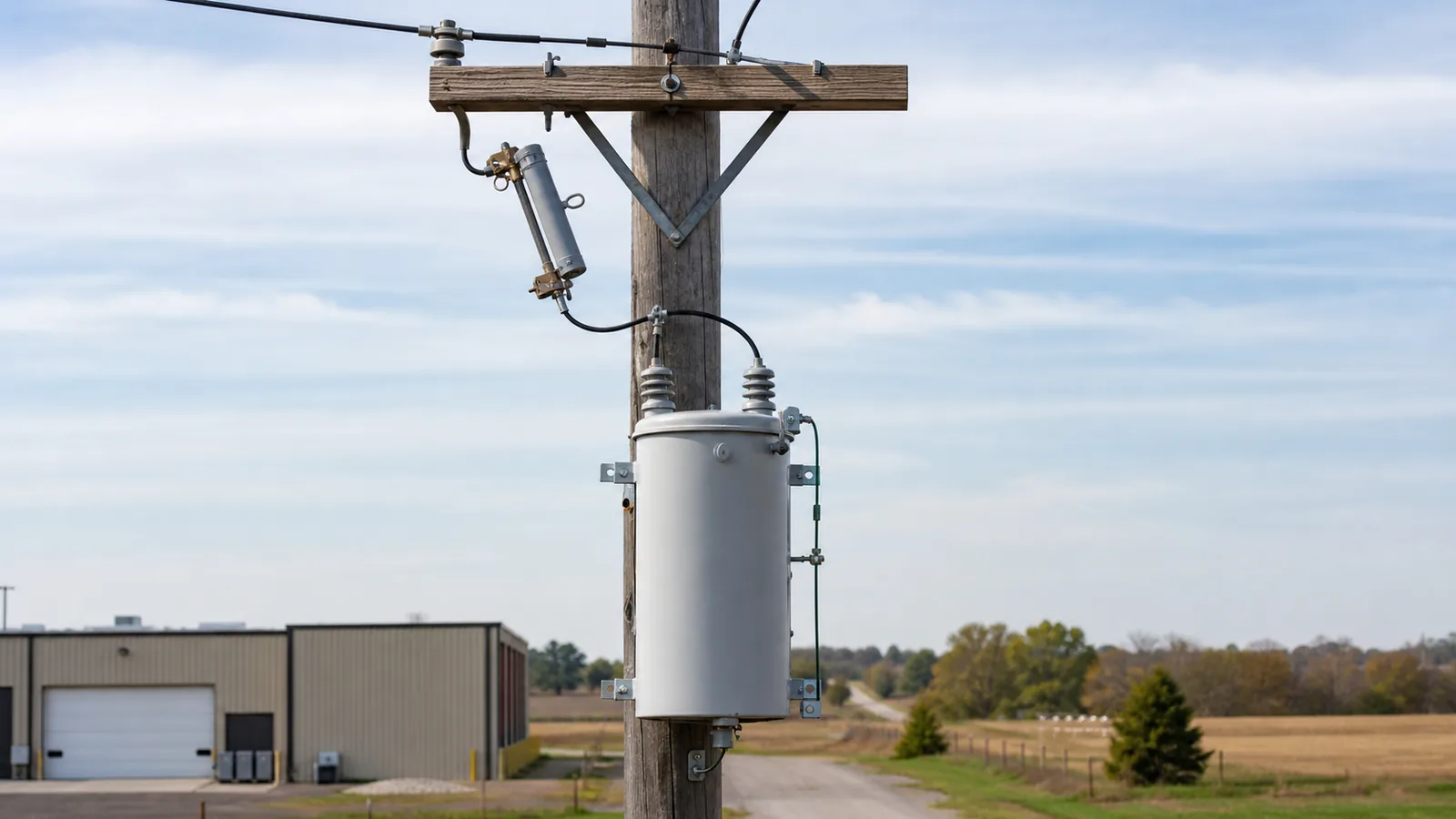
Drop out fuse selection for transformer protection starts with coordination, not with choosing the next fuse-link size above transformer primary current. Define the system voltage and grounding, transformer kVA and impedance, loading and inrush duty, upstream and downstream protection, available fault current, and site environment. Then use the exact manufacturer’s time-current curves to define the acceptable fuse-link range. Only after that should the cutout body, fuse tube, link construction, interrupting duty, insulation, and mounting package be released as one compatible assembly.
XIYA POWER offers drop-out fuse bodies, fuse links, and protected or windproof options, but a product row cannot be selected until the protection inputs are known. The first review should follow this matrix.
| Decision | Required input | Why it matters | Release evidence |
|---|---|---|---|
| System duty | Nominal and maximum voltage, grounding, frequency | Sets voltage and insulation requirements | Single-line diagram and system specification |
| Transformer duty | kVA, primary voltage, winding connection, impedance | Establishes primary current and transformer protection boundary | Approved transformer data sheet |
| Loading | Continuous load, peak load, emergency overload | Defines current the link must carry without operating | Load schedule or feeder study |
| Transients | Magnetizing inrush and cold-load pickup | Defines short- and medium-duration ride-through needs | Manufacturer data and protection study |
| Adjacent protection | Downstream and upstream TCC curves | Defines the coordination window | Device curve files and setting schedule |
| Fault duty | Maximum fault current at the cutout location | Sets the required interrupting performance | Current short-circuit study |
| Environment | Pollution, altitude, temperature, wind, access | Affects insulation and body configuration | Site and project environmental data |
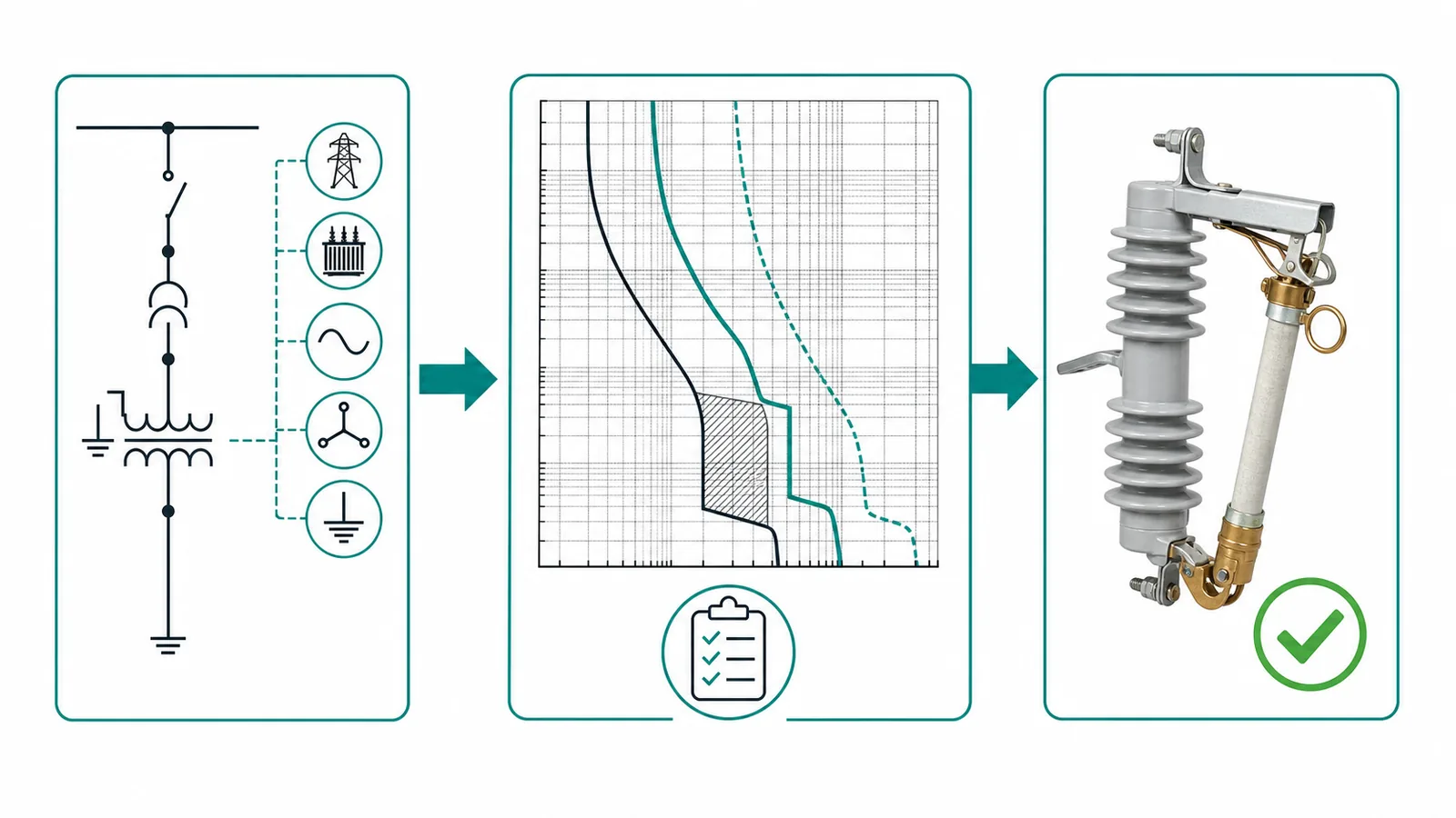
Body selection and link selection are related but separate engineering checks. The body provides the insulator, contacts, hinge, fuse tube support, and mounting interface. The link provides the time-current characteristic that responds to overcurrent. A complete release must show that the selected link coordinates with the system and that the exact link, tube, and body combination is compatible.
Readers who need the operating sequence before the selection process can review how a drop-out fuse cutout operates. This article stays focused on transformer protection selection rather than repeating the basic definition.
For a three-phase transformer, rated primary line current is:
I_primary = kVA / (1.732 x kV_primary)
For a representative 11 kV, 630 kVA three-phase transformer:
I_primary = 630 / (1.732 x 11) = approximately 33.1 A
This is a representative engineering calculation, not an XIYA POWER customer project. It establishes the rated primary-current reference. It does not automatically select a 33 A, 40 A, or 50 A link.
Several boundaries act in opposite directions:
The load and transient requirements create a lower carry-through boundary. Transformer protection and adjacent-device coordination create an upper clearing boundary. The acceptable fuse link is found inside that window using actual curves. Rounding 33.1 A to a standard link size skips the work that decides whether the result will ride through normal events and still clear damaging faults.
The coordination plot should use the exact proposed link’s minimum-melt and total-clearing curves. It should also contain the transformer and adjacent-device boundaries needed to judge both protection and selectivity.
| Coordination boundary | Curve or data required | Risk if omitted | Reviewer action |
|---|---|---|---|
| Maximum loading | Continuous and emergency current with duration | Nuisance operation or accelerated link aging | Keep permitted load duty below the applicable melt boundary |
| Magnetizing inrush | Magnitude and duration from transformer data | Operation during energization | Verify ride-through across the complete inrush region |
| Cold-load pickup | Current multiple and duration | Operation during feeder restoration | Check the full pickup region, not a single current point |
| Transformer withstand | Impedance and approved damage/through-fault curve | Transformer exposure beyond its withstand boundary | Keep total clearing inside the required protection boundary |
| Downstream device | Secondary fuse, breaker, or relay TCC | Loss of selectivity for a secondary fault | Preserve the project-required coordination interval |
| Upstream device | Feeder fuse, recloser, or breaker TCC | Feeder trip or lockout before the transformer branch clears | Confirm the intended feeder operating sequence |
| Cutout fault duty | Maximum available fault current at the location | Interruption beyond the approved assembly rating | Verify the complete proposed cutout and link combination |
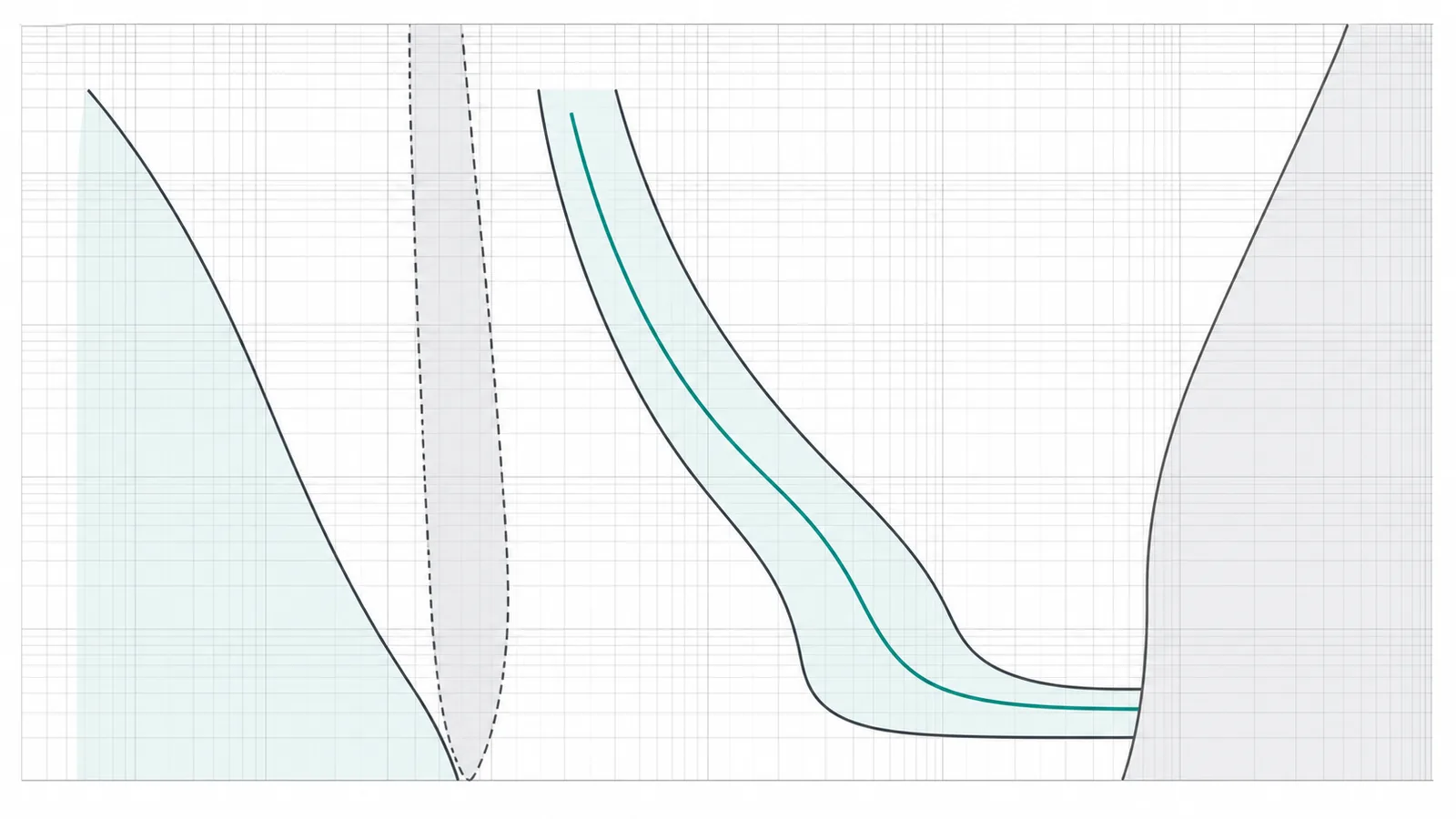
K-type and T-type labels describe relative speed families, but the label is not a universal curve. Actual minimum-melt and total-clearing characteristics vary by manufacturer and product series. Project or utility rules may also constrain the permitted speed class. Select from the curves for the exact proposed link, not from a generic K/T table.
IEC 60282-2 covers requirements for expulsion fuses used on AC systems above 1,000 V. That product-standard framework does not replace the project protection study. Transformer loading, inrush, cold-load pickup, fault duty, and adjacent-device coordination still require project data and manufacturer curves.
Once the coordination window is established, verify the hardware package without merging values from unrelated product rows.
| Package element | Selection check | Common specification error |
|---|---|---|
| Cutout rated voltage and insulation | Match maximum system duty, grounding conditions, and project insulation level | Selecting from nominal voltage alone |
| Body continuous-current rating | Carry maximum permitted load and match the approved tube/contact package | Treating body current as the fuse-link rating |
| Interrupting performance | Complete approved cutout/link combination exceeds available fault current | Mixing body and link data from separate combinations |
| Fuse link | Exact ampere value and speed class pass the TCC study | Choosing the nearest size above primary current |
| Tube and end fitting | Button, thread, rope, arc-control parts, and seating geometry are compatible | Assuming links with the same ampere label are mechanically interchangeable |
| Bracket and body type | Open, protected, enclosed, or windproof body fits the project interface | Assigning accessory data as the full cutout rating |
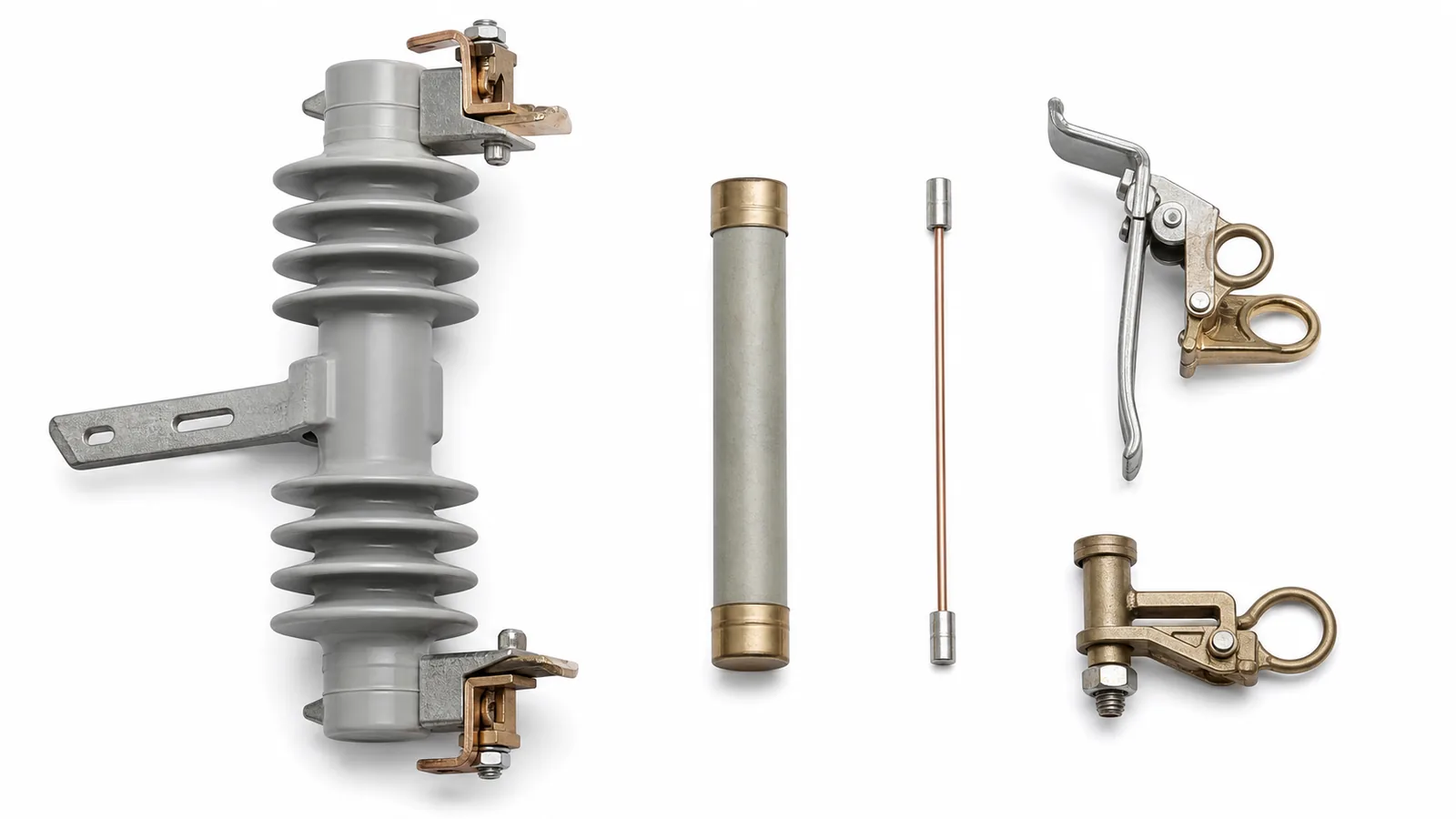
The live XIYA category contains multiple body, link, bracket, protected, and windproof options. Its data deliberately keeps voltage, current, breaking-duty, and accessory rows separate. Follow the same discipline in the RFQ: identify the selected product family and matching technical document before carrying a value into the final specification.
This package review also determines whether another item in the distribution switching equipment hierarchy is the better owner of the duty. A drop-out fuse should not be stretched into a role that requires controlled repeated interruption, remote automation, or a different protection architecture.
Environment can change the required insulation, material, body protection, and mounting package even when the electrical coordination is unchanged.
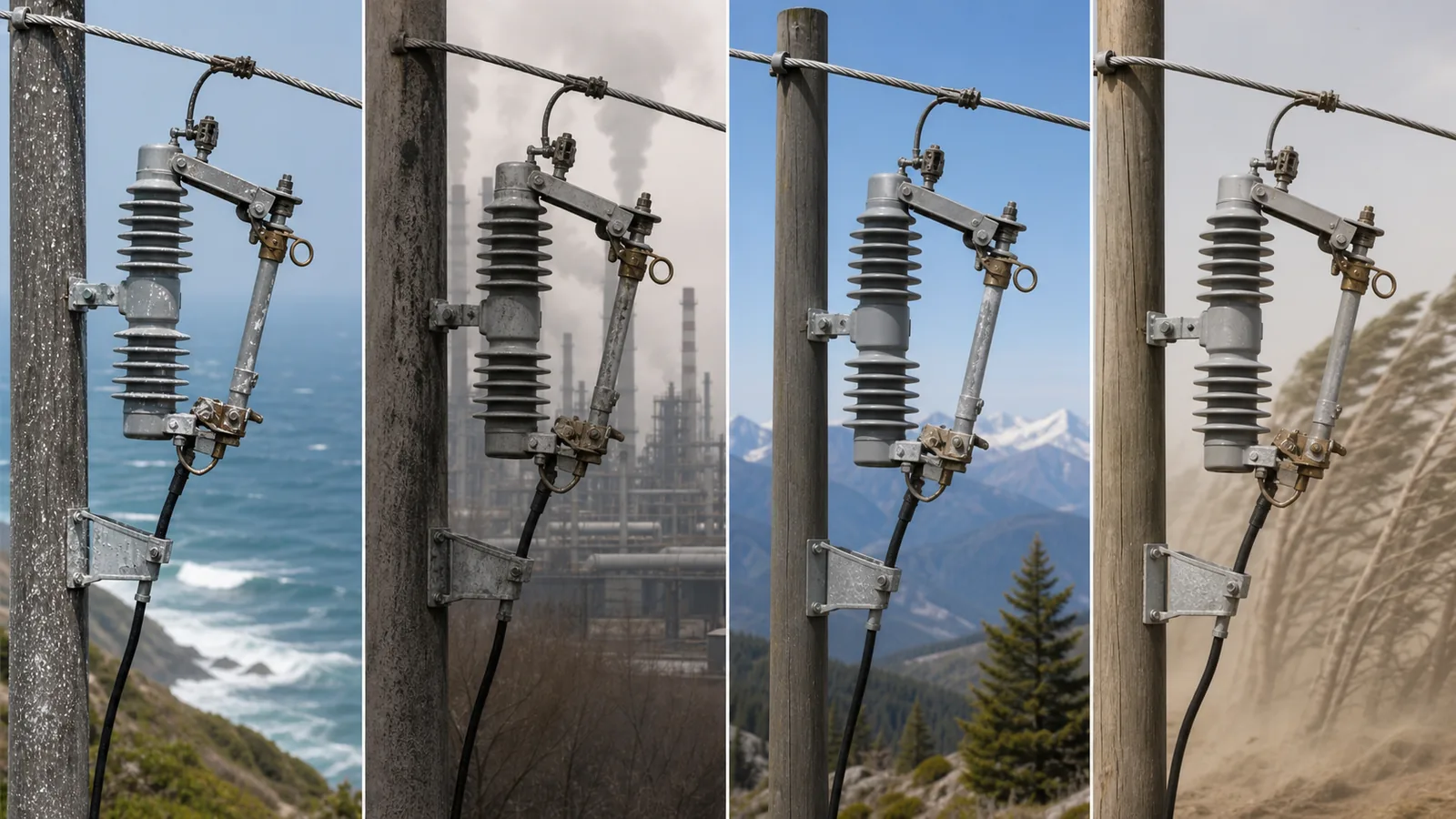
These are selection inputs, not installation instructions. Final pole spacing, clearances, work methods, and grounding procedures belong to the approved installation design and local operating rules.
A transformer fuse RFQ should include the same evidence used to make the selection:
The site’s high-voltage equipment RFQ input guide covers the wider project-data structure; this article adds the transformer-specific protection and coordination evidence.
Consider a representative inquiry for the 11 kV, 630 kVA transformer calculated earlier. It states a 12 kV cutout class, a body current class, and a nominal link value based on the 33.1 A primary current. It omits available fault current, the transformer inrush and damage boundaries, cold-load pickup, and adjacent-device TCC curves. It also omits pollution class and altitude. This is a representative engineering review, not an XIYA POWER customer project.
The correct action is to hold technical release. Fault duty cannot be verified without the short-circuit result; protection and selectivity cannot be confirmed without the curves; and the insulation/body package cannot be finalized without environmental data. Issuing the nearest standard link size would create an unsupported selection.
When those inputs are ready, send the project data pack to XIYA POWER for model matching, document review, and quotation. The handoff should identify what is confirmed, what remains provisional, and which product document controls each released value.
For a three-phase transformer, divide rated kVA by 1.732 times primary line-to-line kV. A 630 kVA transformer at 11 kV gives approximately 33.1 A. The result is a coordination input, not the final link rating.
No. The selected link must also ride through permitted loading, inrush, and cold-load pickup while protecting the transformer and coordinating with adjacent devices.
The body rating applies to the cutout current path and compatible hardware. The fuse-link ampere rating applies to the replaceable protective element selected from the TCC study. They are separate values within one approved assembly.
It determines whether the complete proposed cutout and fuse-link combination has adequate interrupting performance. The value must come from a current short-circuit study for the applicable system configuration.
They represent different speed families, with K generally faster and T generally slower. The final choice depends on the exact manufacturer’s curves, transformer boundaries, and feeder coordination rules.
Include system, transformer, loading, inrush, fault-current, TCC, environment, hardware-interface, standards, drawing, quantity, and spare data. Missing fault or curve information should hold technical release rather than be filled with assumptions.



