Quotation form
Send an inquiry
Start with the basics. Our team can follow up for missing drawings, standards or packing details.
Submitted details are used only for quotation, technical review and project communication.

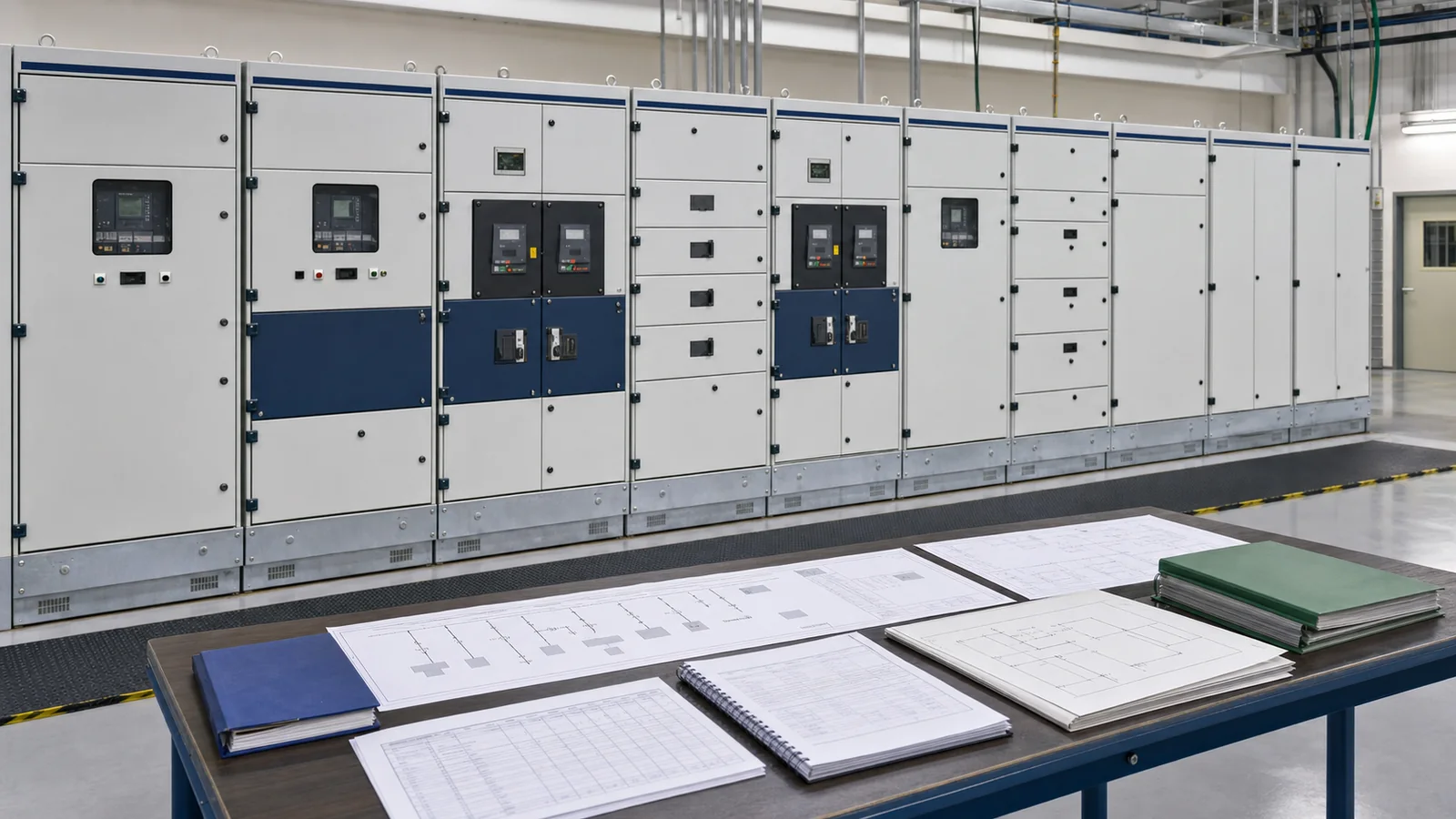
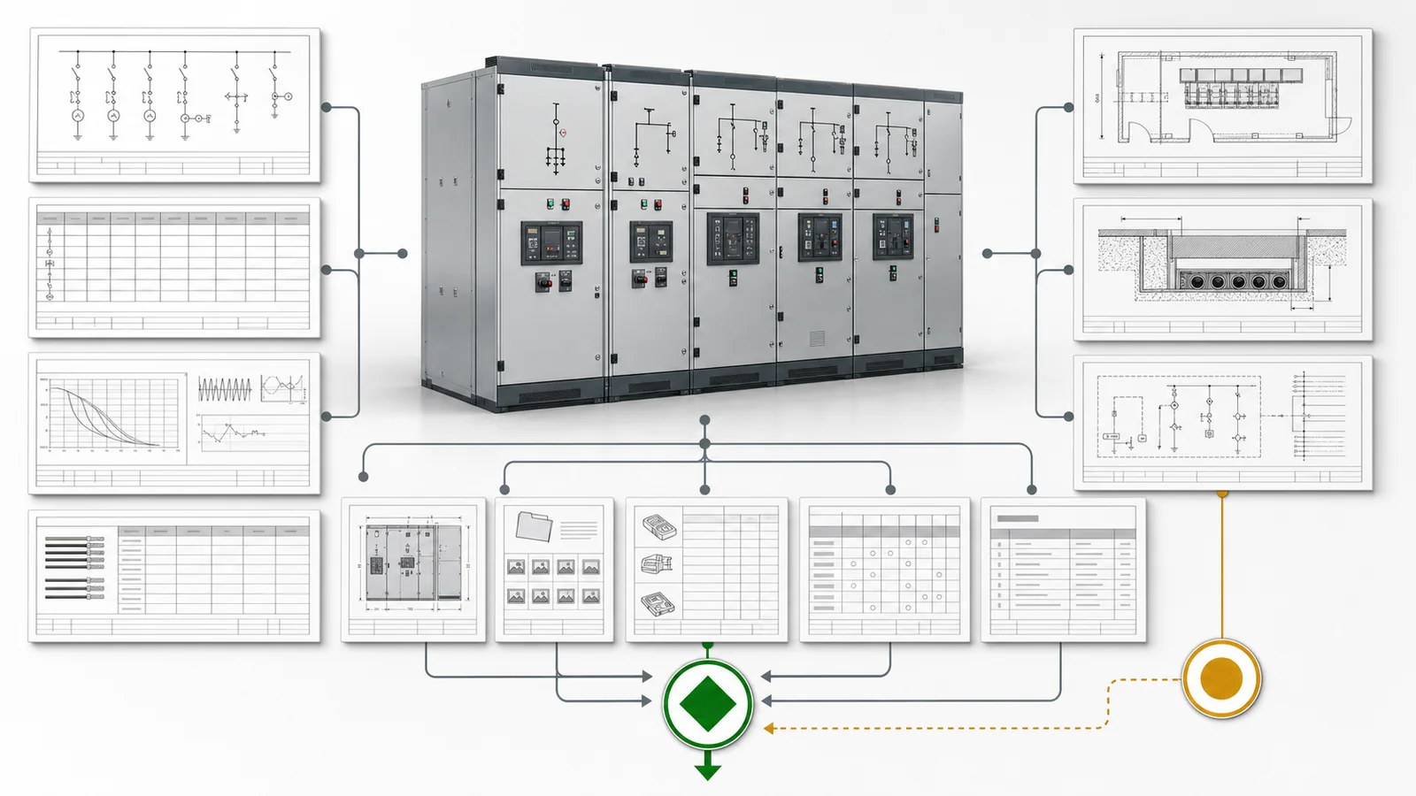
A quotation-ready medium-voltage switchgear RFQ defines the lineup, not just a voltage and bus current. It combines the current single-line diagram, bay schedule, system and fault basis, cable and room interfaces, CT/VT and protection responsibilities, control and communication boundary, assembly requirements, and release evidence. A request for 12 kV switchgear, 1,250 A cannot show how many bays are needed, what each bay does, which fault duty applies, or whether the cables and protection system fit. Start with the complete switchgear cabinet range, then issue the project data below as one controlled package.
The SLD is the functional source for the lineup. It should show utility, transformer, generator, or other incoming sources; bus sections and couplers; incomers, outgoing feeders, metering/VT, earthing, capacitor, or other functional units; normal-open points; and the normal and contingency operating states. Number every position so the SLD, bay schedule, load list, protection schedule, and supplier offer refer to the same bay.
The bay schedule adds the information a one-line symbol cannot carry. This selection matrix keeps the buyer’s required input separate from the supplier’s design output:
| SLD or bay item | Required input | Supplier output | Hold condition |
|---|---|---|---|
| Incoming source | Connection point, transformer/source data, operating state | Incomer functional unit and interfaces | Source or duty basis missing |
| Main bus and sections | Section arrangement, normal state, transfer philosophy | Busbar and sectionalizing arrangement | Contingency state not defined |
| Bus coupler | Normally open/closed state and permissives | Device, controls, and interlocks | Transfer sequence unresolved |
| Outgoing feeder | Load role, normal current, cable and protection responsibility | Feeder functional unit | Feeder schedule incomplete |
| Metering/VT function | Metering and voltage-sensing purpose | Instrument and secondary arrangement | Accuracy/burden responsibility open |
| Earthing function | Required location and operating sequence | Earthing device and interlocks | Maintenance boundary unclear |
| Future position | Quantity, extension side, timing, and provisional duty | Space, bus extension, and interface provision | Future scope is only a note |
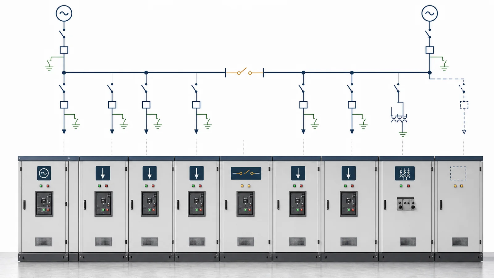
Show where the supplier’s primary and secondary scope begins and ends. Incoming and outgoing cable terminations, external protection panels, station batteries, SCADA gateways, arc ducts, bus connections, loose accessories, and field cabling should each have an owner. If an architecture is still open, state the constraints and mark it supplier to propose; do not let bidders silently quote different functional lineups.
Build the rating schedule from the approved load-flow, insulation-coordination, and short-circuit study rather than copying a catalog row. The MV switchgear ratings guide explains the individual rating families; the RFQ must assign them to the assembly and each functional unit.
| Rating decision | Lineup input | Review boundary | Release evidence |
|---|---|---|---|
| System/equipment voltage and frequency | Nominal network values, highest voltage for equipment, frequency, grounding | System values and equipment ratings are not interchangeable | Project specification and adopted standard |
| Main-bus normal current | Maximum normal and contingency loading | Bus rating does not set every feeder rating | Load-flow basis and supplier rating schedule |
| Feeder normal current | Current by numbered bay | Each feeder may differ from the main bus | Load/transformer/cable schedule |
| Short-time withstand | RMS fault current and duration at the assembly | Assembly, bus, earthing circuit, and components must coordinate | Short-circuit study and manufacturer data |
| Peak withstand/making | Required peak duty from the approved basis | Do not derive a universal multiplier in the RFQ | Study value and offered ratings |
| Breaking duty | Calculated duty at each switching device | Rated breaking capacity must cover the assigned duty | Study and component evidence in the assembly |
| Insulation | Required impulse and power-frequency levels | Coordinate assembly, components, cables, and site basis | Insulation schedule and applicable evidence |
The official IEC 62271-200:2021 page states that the standard applies to prefabricated AC metal-enclosed switchgear and controlgear above 1 kV through 52 kV, up to 60 Hz, for indoor or outdoor installation. Its public revision summary notes more precise treatment of loss-of-service-continuity categories and internal-arc testing. That scope helps identify the assembly standard; it does not select the project’s LSC, IAC, accessibility, arc duration, or service requirements.
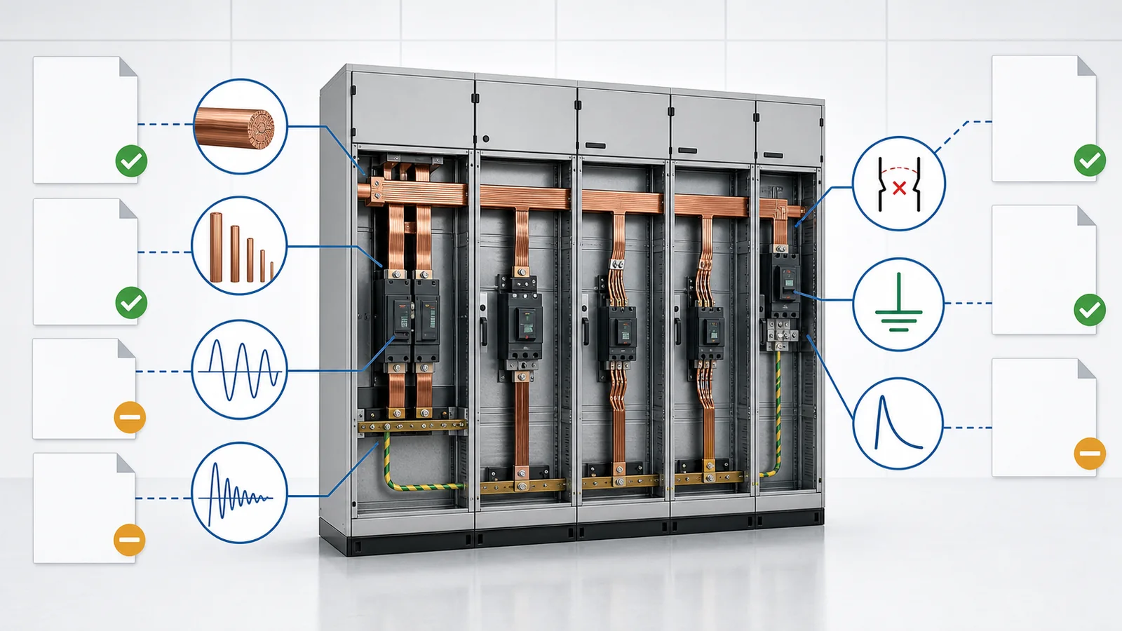
Record the source document, revision, and owner for every value. When a study is pending, use an owned clarification and milestone. Do not ask the supplier to select a convenient fault rating and later treat that assumption as a project decision.
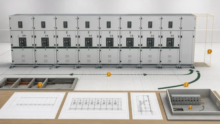
Cable data affects the termination compartment, CT or sensor position, gland/entry plate, earthing arrangement, and cabinet footprint. Provide enough information for feasibility and quotation while leaving detailed routing and bending verification to the later cable-interface review.
| Interface | Buyer input | Supplier confirmation |
|---|---|---|
| Entry direction | Top/bottom entry and any mixed-bay requirement | Offered entry construction and affected bay dimensions |
| Cable construction | Insulation type, conductor material, single/three-core, screened/armoured form | Compatible termination interface |
| Quantity and size | Number per phase and conductor size by feeder | Termination capacity and arrangement |
| Screen/armour earthing | Bonding philosophy and station-earth boundary | Earthing points and supplied hardware |
| Termination scope | Client/supplier termination, connector, lug, gland, and test-access boundary | Included parts and exclusions |
| CT/sensor interface | Required location or design responsibility | Physical relationship to cable and termination |
| Room/trench envelope | Available entry zone, trench/duct relationship, obstructions, and access limits | Base frame, entry plate, transport, and installation assumptions |
| Future extension | Extension side, cable approach, and reserved interfaces | Bus, base, and enclosure provisions |
Do not substitute bottom cable entry for a cable schedule. The supplier still needs the cable form, count, size, termination technology or responsibility, earthing arrangement, and available interface envelope. Conversely, the RFQ does not need to calculate a final bend radius or internal route when those drawings are not yet approved; it should identify the responsible party and make the detailed drawing a release hold point.
CTs, VTs, relays, trip/close circuits, interlocks, metering, and communication form one responsibility chain. Allocate the design input, supplied hardware, factory verification, and site interface for each block.
| Function | Project must define | Supplier must return | Open-item risk |
|---|---|---|---|
| CTs and sensors | Protection/metering purpose, ratios/classes/burdens or delegated design basis | Offered cores, data, location, and terminals | Relay or meter cannot be verified |
| VTs and metering | Sensing arrangement, accuracy/burden, isolation, and metering boundary | Offered arrangement and secondary protection | Bay count and secondary scope change |
| Protection | Required functions, zones, grading responsibility, and relay-model authority | Relay proposal, I/O, schematics, and deviations | Device selection precedes protection intent |
| Trip/close/control power | Supply type/value, source, range, supervision, and backup responsibility | Load data, wiring, terminals, and failure behavior | Coils and controls may not match station supply |
| Interlocks | Operating philosophy, permissives, maintenance and earthing sequence | Mechanical/electrical logic and matrix | Unsafe or unusable sequence remains hidden |
| Indication/metering | Local displays, status points, measurements, and accuracy | Device list and panel arrangement | Quotations carry different scope |
| SCADA/communication | Physical layer, protocol, point-list owner, commands, time source, security boundary | Interfaces, supported data, test boundary, and exclusions | SCADA ready has no testable meaning |
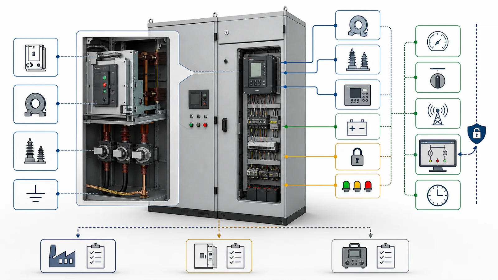
The project engineer or protection consultant should own the required functions and coordination basis. The supplier may select or propose CTs, VTs, relays, meters, and communication hardware when that responsibility is explicitly delegated and the input criteria are complete. Do not require the cabinet manufacturer to invent settings, protection zones, or remote-command authority from a one-line symbol.
Record the chosen or constrained cabinet architecture without repeating the separate architecture comparison. State indoor/outdoor use, fixed or withdrawable switching device, compartment and partition expectations, service-continuity requirement, accessible sides, internal-arc requirement where applicable, arc-exhaust boundary, earthing-switch scope, future extension, service conditions, and any room interface that changes the assembly.
Then compare one offered assembly revision against one data pack:
| Release record | Required match | Hold condition |
|---|---|---|
| Offer SLD and bay schedule | Bay count, sequence, roles, devices, and future scope | Supplier lineup differs from project functions |
| GA and room interface | Dimensions, weights, access, cable entry, arc interface, and shipping splits | Civil/interface assumptions not declared |
| Rating schedule | Assembly, bus, feeder, breaker, insulation, and service duties | Values are incomplete or drawn from another series |
| Primary/secondary drawings | CT/VT, protection, control, terminals, communication, and interlocks | Responsibility chain is inconsistent |
| Type/design evidence | Offered assembly construction and declared ratings/classes | Applicability is asserted but not documented |
| Routine-test and inspection plan | Contract tests, acceptance source, unit traceability, and records | FAT scope is left until manufacture |
| Deviation matrix | Every exception, option, and open clarification | Verbal exception remains outside the offer |
The general high-voltage equipment RFQ checklist covers commercial terms, packing, labels, delivery, and the wider document register. For the limited purpose of distinguishing insulation resistance from power-frequency withstand evidence, use the earlier switchgear test comparison. CAB-01 does not replace a full FAT plan.
Representative engineering review, not an XIYA POWER customer project. An inquiry supplies an 11 kV nominal system, 12 kV equipment class, 1,250 A main bus, 25 kA for 3 s short-time withstand, 110 VDC control, one incomer, one bus-section/coupler position, and six outgoing feeders. These are illustrative RFQ inputs, not a XIYA product rating or recommended universal design.
The data establishes a useful system class, bus-current target, short-time duty, control-supply input, and preliminary functional-unit count. It does not release the lineup. The review still needs:
The appropriate response is a controlled clarification register and quotation hold, not a guessed standard lineup. To review cabinet feasibility and the supply boundary, send XIYA POWER the SLD, bay schedule, studies, cable data, room interface, protection/control philosophy, communication boundary, service requirements, and evidence register. Review does not promise final compliance before the offered assembly is verified.
Show every source, bus section, coupler, numbered functional bay, metering/VT and earthing position, normal-open point, normal and contingency state, future bay, and primary supply boundary. The bay schedule then adds current, cable, protection, and interface responsibilities.
No. State the assembly short-time RMS duty and duration, required peak withstand, and device breaking/making duties from the approved study. Coordinate those values across the bus, switching devices, earthing circuit, and functional units.
Provide entry direction, cable construction, conductor material, number and size per phase, termination/screen/armour earthing method, gland or entry-plate responsibility, CT/sensor relationship, and the available room/trench interface.
The project should define the functions, zones, accuracy or performance criteria, and responsibility. The supplier can design or propose hardware when delegated inputs and approval rules are explicit; settings and coordination remain project-controlled unless separately assigned.
Yes, when they are project requirements. State the required service-continuity, accessibility, internal-arc duty, duration, accessible sides, and exhaust interface under the adopted standard. Do not expect a cabinet family name to select them automatically.
Require the offer SLD and bay schedule, GA/interface drawing, rating schedule, primary and secondary schematics, CT/VT and protection data, interlock matrix, applicable type/design evidence, proposed routine tests, and a complete deviation/open-item response.