Quotation form
Send an inquiry
Start with the basics. Our team can follow up for missing drawings, standards or packing details.
Submitted details are used only for quotation, technical review and project communication.

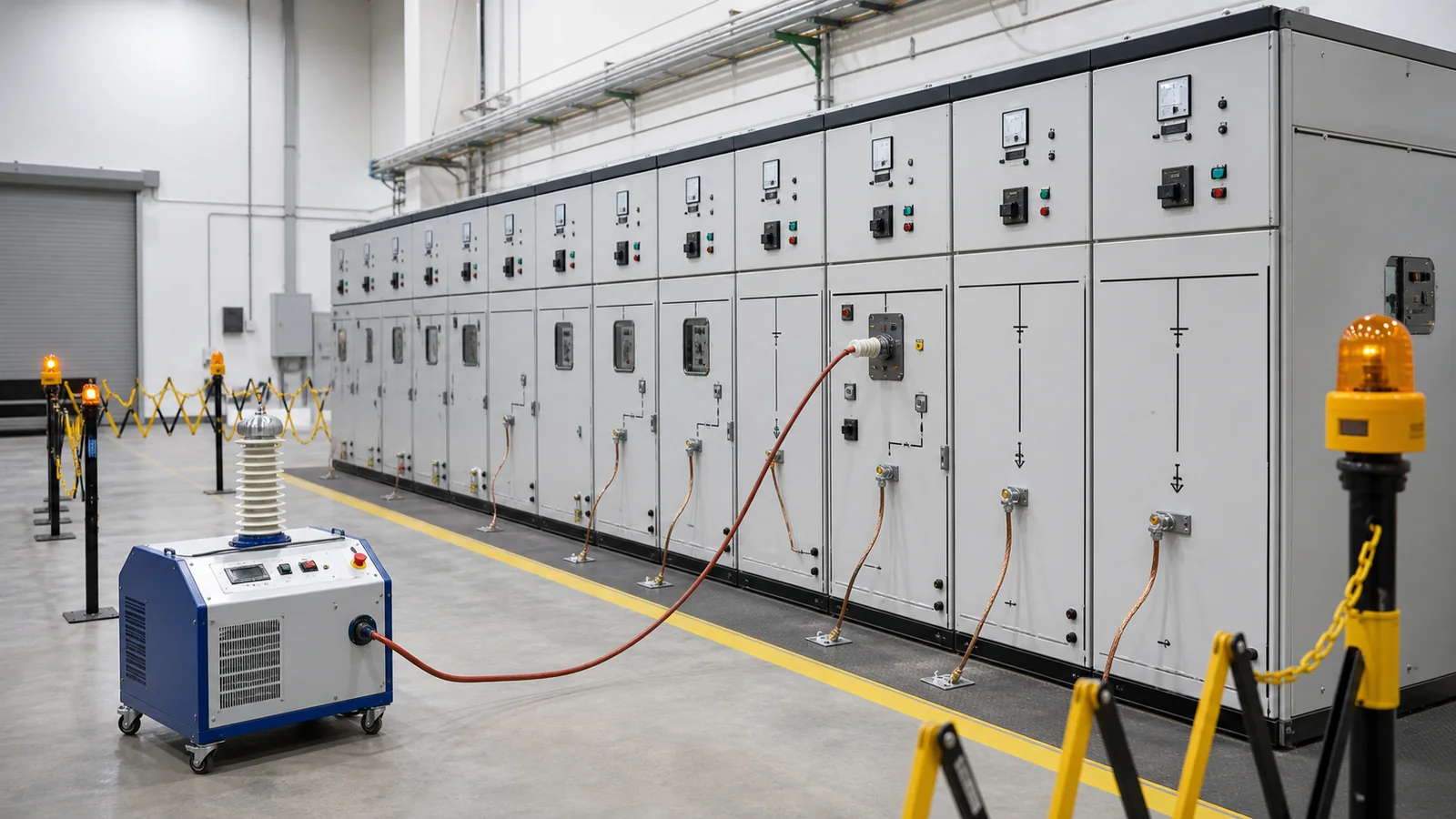
An insulation resistance test applies controlled DC voltage and reports resistance; a power-frequency withstand test applies specified AC stress and records whether the switchgear withstands it without disruptive discharge. The first is a diagnostic or screening measurement. The second is a proof test. They are complementary, not interchangeable. A high megohm reading cannot prove AC withstand capability, and a passed AC withstand test does not create a useful condition baseline. For any medium-voltage switchgear cabinet, the approved procedure must define the test voltage, connection, exclusions, environment, acceptance source, and release authority.
Use the comparison as a release matrix, not as permission to select test settings. IEC 62271-200:2021 covers AC metal-enclosed switchgear above 1 kV and up to and including 52 kV, but the applicable project specification, manufacturer instructions, and approved test procedure still govern the test applied to a particular assembly.
| Review point | Insulation resistance | Power-frequency withstand | Release implication |
|---|---|---|---|
| Question answered | Is DC leakage through the measured insulation path consistent with the approved criterion or baseline? | Can the configured test object sustain the prescribed AC stress? | Neither result replaces the other |
| Source | Controlled DC from an insulation-resistance tester | Controlled power-frequency AC from a suitable test set | The source and waveform must match the procedure |
| Output | Resistance plus elapsed time and test conditions | Withstand result plus observations and protection response | A bare value or a bare pass is incomplete evidence |
| Typical role | Screening, baseline, comparison, and condition review | Factory, site, or post-repair proof testing where specified | Factory and site requirements may differ |
| Acceptance source | Approved criterion, comparable baseline, phase/path comparison | Specified voltage, duration, configuration, and pass/fail rule | Do not invent a universal threshold |
| Common misuse | Reading megohms without configuration, temperature, or exclusions | Reusing a factory level as an automatic site retest level | Place the test on hold until the basis is confirmed |
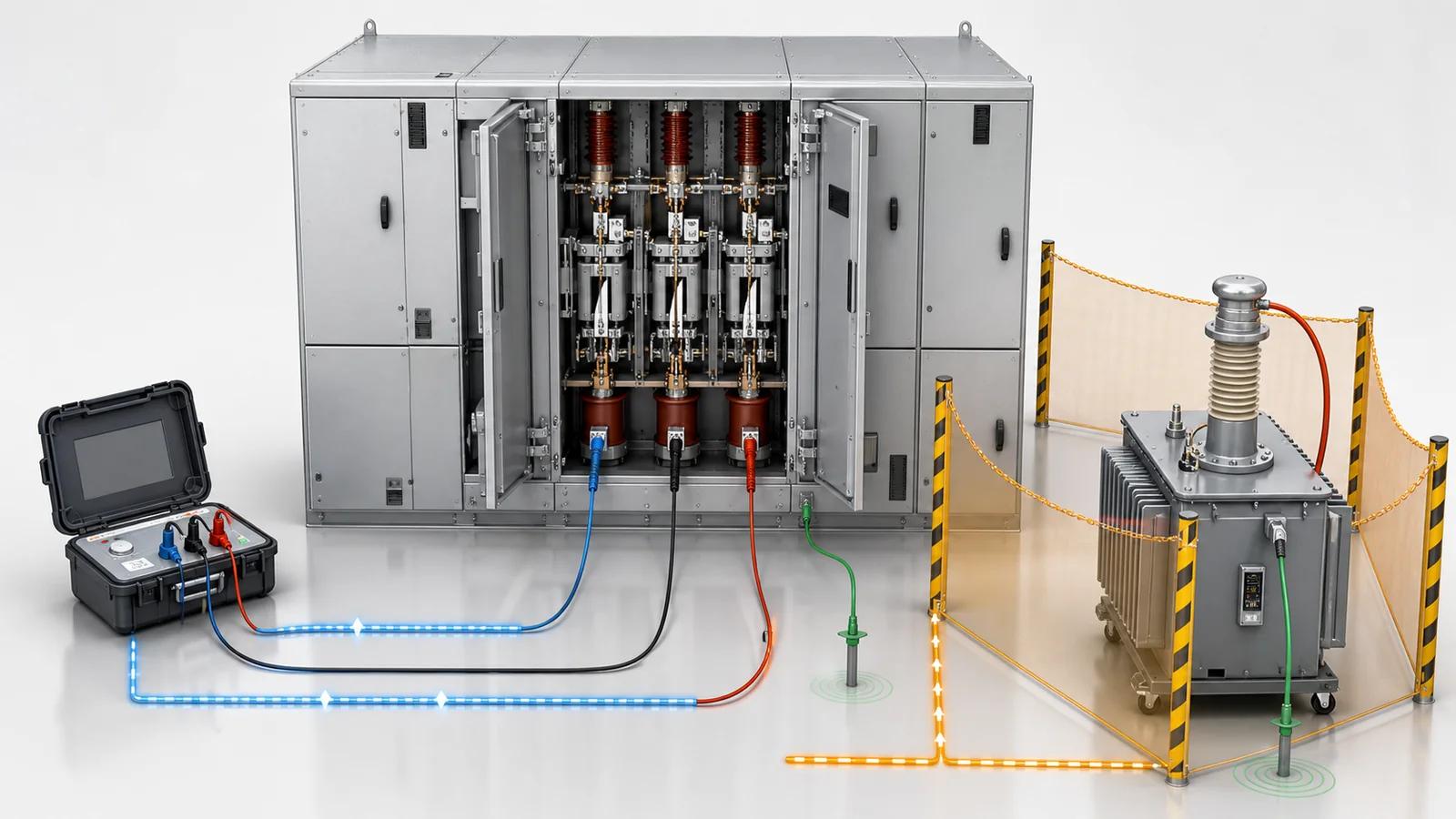
The terminology matters. Insulation resistance is not main-circuit or contact resistance, which measures the closed current path and joints at much lower resistance. Power-frequency withstand is also not DC hipot, VLF, partial-discharge, or tan-delta testing. Those methods answer other insulation questions.
A quick diagnosis table helps reviewers stop an invalid record before it reaches the release pack:
| Symptom | First test or check | Likely cause to investigate | Next action |
|---|---|---|---|
| IR phases differ materially | Confirm test connection, environment, and exclusions | Moisture, contamination, connected device, lead routing, or insulation condition | Inspect, correct the boundary, and repeat only under the approved procedure |
| IR sheet has values but no conditions | Compare the sheet with the test diagram and instrument record | Incomplete evidence rather than proven insulation failure | Hold interpretation and recover or repeat the record |
| AC test trips or produces abnormal sound | Make the system safe and preserve event data | Test-set issue, incorrect connection, surface discharge, or dielectric defect | Raise a nonconformance; investigate before any retest |
AC sheet says only pass |
Check voltage, duration, configuration, and observations | Missing traceability | Request the complete test record before technical release |
The responsible test authority owns the switching, grounding, connection, and safety sequence. An article cannot replace the site safety plan or equipment-specific procedure. The release check should nevertheless expose every boundary that can invalidate the result or expose connected equipment to the wrong stress.
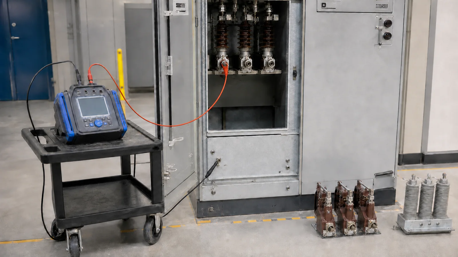
The cabinet rating provides context, not an automatic test setting. A reviewer who needs that context should first confirm the distinctions in how to read medium-voltage switchgear ratings. The test value and sequence must then come from the governing documents for the actual assembly and test stage.
When DC voltage is applied, charging and absorption currents decay before the remaining leakage current becomes dominant. That is why elapsed time and prior discharge matter. Surface moisture, contamination, temperature, connected devices, test-lead routing, and guarding can change the measured path even when the bulk insulation has not changed.
| Record field | Why it matters | Review action when missing |
|---|---|---|
| Test voltage and elapsed time | Results from different settings or times are not directly comparable | Hold trend comparison |
| Phase-to-earth or phase-to-phase connection | Combined paths can hide a local issue | Request the as-tested diagram |
| Included and excluded equipment | Arresters, transformers, cables, and electronics change the path | Reconstruct the boundary or repeat the test |
| Temperature and humidity | Both affect surface and bulk leakage | Mark the result as condition-incomplete |
| Surface condition and guarding | Dust, moisture films, and surface leakage can dominate | Inspect, clean if authorized, and document guard use |
| Instrument and calibration status | Establishes traceability | Confirm model, serial number, and valid calibration reference |
| Result and discharge confirmation | Links the measured value to a safe close-out | Record each path and the completed discharge/grounding step |
| Baseline or acceptance source | Turns a number into a controlled decision | Identify the approved criterion or comparable maintenance record |
There is no universal acceptable megohm value for every MV lineup. Interpretation depends on insulation system, rated voltage, applied DC voltage, elapsed time, conditions, configuration, and the agreed criterion. Phase comparison and trend analysis are useful only when those variables are comparable. A low or uneven reading is a diagnostic signal; it is not automatically proof of a failed AC insulation system. A high reading is similarly bounded: it does not authorize the next proof test.
The AC test applies substantially different electrical stress. Its voltage, duration, connection, and any reduced site or retest level must be approved for the equipment and test stage. Do not copy a product manual’s value into another lineup or infer it from the basic switchgear rating definitions.
| Test phase | Required control | Evidence retained |
|---|---|---|
| Pre-test release | Verify diagram, exclusions, grounds, clearances, personnel, and test-set protection | Signed checklist and approved revision |
| Controlled ramp | Raise voltage from zero according to the procedure | Start time and ramp record |
| Prescribed hold | Observe current, protection, sound, and visible activity | Hold timing and observation log |
| Abnormal response | Stop, ramp down, de-energize, discharge, ground, and preserve evidence | Event record and nonconformance |
| Controlled ramp-down | Return voltage to zero before source isolation | End time and operator confirmation |
| Discharge and restoration | Ground the test object, remove leads, reconnect exclusions, and restore interlocks | Signed restoration checklist |
| Retest | Use only an approved scope, level, and authorization | Corrective action and retest approval |
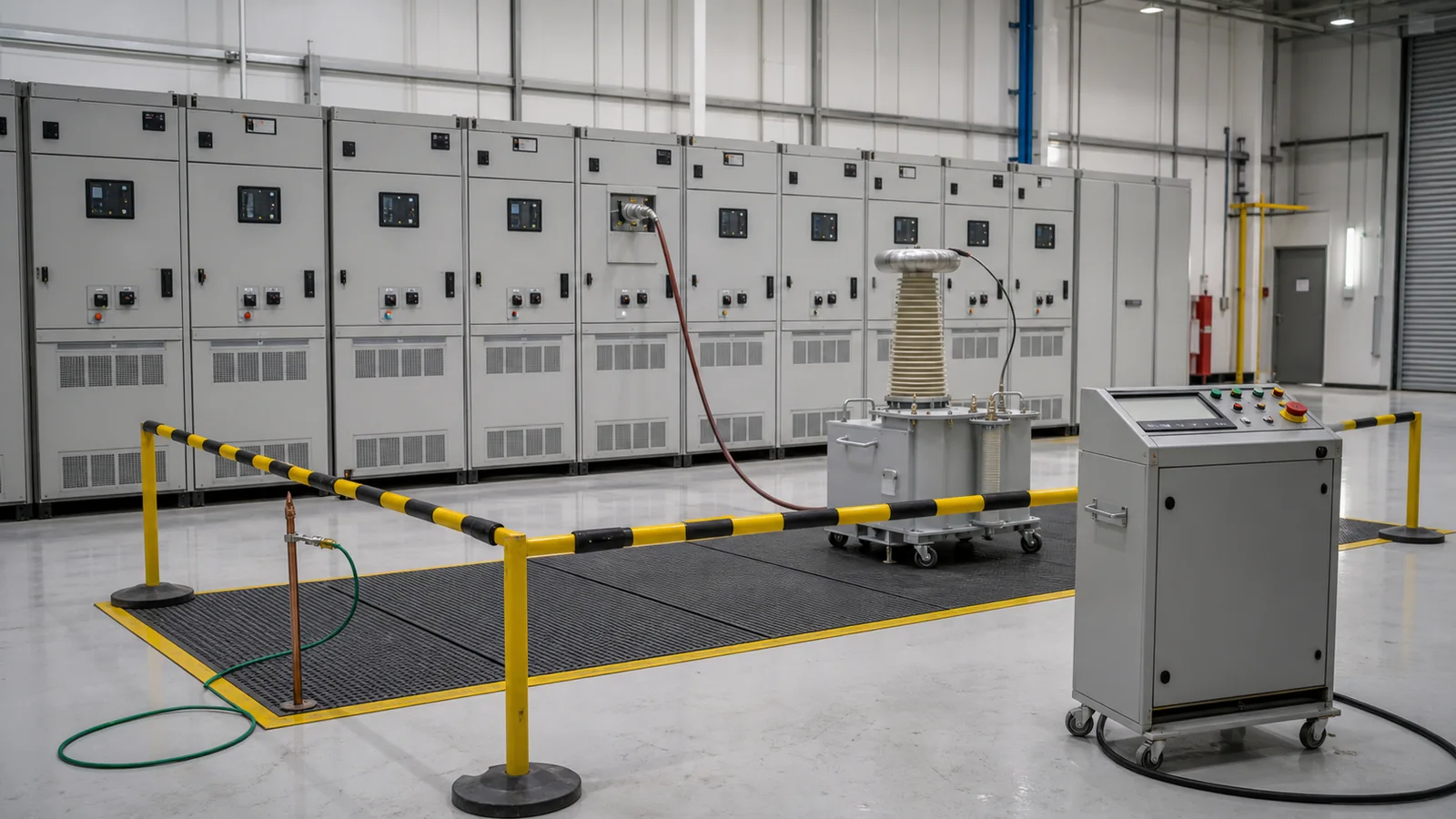
A favorable IR record does not remove any of these controls. It says only that DC leakage was acceptable under the recorded configuration and conditions. It cannot show that every connected component is suitable for AC test stress or that the assembly will withstand the prescribed proof-test condition.
This test may appear within a wider switchgear factory acceptance test, but CAB-10 owns only the electrical test distinction. Mechanical operations, wiring checks, protection tests, inspection points, deviations, and shipment release still belong to the full FAT plan.
The result should support a bounded decision, not a broad claim about service life or every insulation defect.
| Observed record | What it supports | What it does not prove | Next controlled action |
|---|---|---|---|
| Complete, comparable IR record | DC leakage path is consistent with its approved criterion | AC withstand or absence of every latent defect | Retain as baseline; proceed only if the next test is separately released |
| Low or uneven IR with moisture or contamination | A path needs inspection | Root cause or permanent insulation failure | Inspect, clean or dry as authorized, then repeat under comparable conditions |
| IR configuration or environment unknown | A measurement occurred | Interpretability or comparison | Hold; recover evidence or repeat the measurement |
| AC test completed with no disruptive discharge under the approved condition | The configured object withstood that prescribed test | Long-term life, partial-discharge state, or performance under a different condition | Complete restoration and file the evidence |
| Trip, abnormal current, sound, or visible discharge | An abnormal test event occurred | Exact location or cause | Make safe, investigate, and raise a nonconformance |
| Cleaning or repair followed by proposed retest | Corrective action was attempted | Closure of the original cause | Obtain approved retest scope and authorization |
Representative diagnostic example, not a XIYA project or commissioning record. A 12 kV metal-enclosed lineup has phase-to-earth and phase-to-phase IR entries, but the sheet omits temperature, humidity, connection diagrams, and confirmation that voltage transformers, surge arresters, or control-power transformers were isolated as required. No measured field values or pass result are claimed here.
The correct decision is to hold interpretation and release. Reconstruct the test boundary, check the instrument and calibration record, inspect the relevant surfaces, and repeat only under an approved procedure if the missing evidence cannot be recovered. Any required AC withstand test starts only after its own preconditions are accepted. This preserves useful engineering detail without turning an illustrative record review into fabricated first-hand experience.
The release package must connect the test result to the exact lineup, configuration, procedure, tools, and acceptance source. A practical data pack includes:
| Deliverable | Minimum evidence |
|---|---|
| Governing basis | Approved procedure, standard hierarchy, purchaser project specification, and acceptance criteria |
| Equipment identity | Lineup, panel designations, serial identifiers, and current drawing revision |
| Test boundary | As-tested diagram, connections, included equipment, and signed exclusion list |
| Conditions | Temperature, humidity, surface condition, and test time |
| Tools | Insulation tester or AC test set identity, serial number, settings, and calibration status |
| Execution record | IR elapsed time and paths, or AC ramp/hold/ramp-down data and observations |
| Result | Raw readings or withstand decision for every required configuration |
| Exceptions | Protection response, deviations, nonconformance, corrective action, and retest authorization |
| Restoration | Discharge, grounding, reconnection, interlock restoration, and return-to-service checks |
| Release | Test engineer, witness where required, approval authority, date, and hold/conditional/released status |
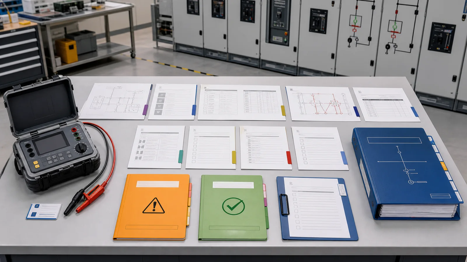
The complete evidence pack is more valuable than an isolated certificate line because it lets another reviewer reproduce the decision basis. To align a cabinet configuration with an approved test boundary, send the switchgear specification, single-line diagram, test requirements, and record template through XIYA POWER’s technical inquiry channel. The review should confirm configuration and evidence requirements; it should not promise acceptance of an unverified result.
IR applies controlled DC and reports resistance under recorded conditions. Power-frequency withstand applies prescribed AC stress and records whether the configured test object withstands it. One is diagnostic; the other is a proof test.
No. Low DC leakage does not prove performance under AC proof-test stress. Where both are required, each needs its own approved connection, settings, observations, and acceptance decision.
Depending on the procedure, the list may include surge arresters, voltage transformers, control-power transformers, cables, sensors, electronics, and auxiliary circuits. The test authority must confirm and record the exact exclusions.
There is no single value for every lineup. Use the approved acceptance criterion and interpret the result with the test voltage, elapsed time, insulation system, environment, connection, exclusions, and comparable baseline.
Installation, connected equipment, environmental conditions, prior service, and the governing field-test rules differ from factory conditions. The applicable standard, project specification, OEM instructions, and approved site procedure determine the field level and sequence.
Request the procedure, equipment identity, as-tested diagram, exclusion list, environmental record, instrument and calibration details, settings, raw results, observations, deviations, corrective actions, retest authorization, restoration checklist, and signed release status.