Quotation form
Send an inquiry
Start with the basics. Our team can follow up for missing drawings, standards or packing details.
Submitted details are used only for quotation, technical review and project communication.


A switchgear factory acceptance test (FAT) is a controlled pre-shipment review of the manufactured assembly against the approved purchase specification, drawings, data sheets, applicable standards, and inspection and test plan (ITP). It checks whether the actual lineup matches the ordered configuration and whether the specified mechanical, wiring, control, protection, communication, and electrical checks have been completed with traceable records.
A FAT is not a type test, design certificate, site acceptance test, or commissioning exercise. It cannot prove cable installation, site earthing, network coordination, or functions that depend on the final switch room. Its scope and acceptance limits must be agreed before witnesses arrive.
| Activity | Evidence or Equipment | Main Question |
|---|---|---|
| Design/type evidence | A representative design and its reports | Has the design demonstrated the required standard performance? |
| Routine factory tests | The manufactured unit or assembly | Does production meet the specified routine requirements? |
| Project FAT | The ordered lineup and approved project documents | Does this configuration match the order and perform the witnessed functions? |
| Site acceptance test | Installed equipment, cables, auxiliaries, and interfaces | Was the system installed and connected correctly? |
| Commissioning | Complete system under the approved energization plan | Are settings, coordination, operating interfaces, and the system ready for service? |
| Symptom | First Test | Likely Cause | Next Action |
|---|---|---|---|
| Nameplate differs from the approved data sheet | Compare the nameplate, bill of materials, and latest drawing revision | Wrong component, obsolete document, or unapproved substitution | Stop the affected check; record a deviation and obtain an approved disposition |
| A breaker truck does not move smoothly through its intended positions | Verify truck identity, rails, stops, shutters, and mechanical alignment | Adjustment issue, shipping brace, obstruction, or mismatched truck | Correct under the assembly procedure and repeat the full movement/interlock sequence |
| Secondary injection does not produce the expected trip output | Confirm the test setup, loaded settings, binary mapping, auxiliary supply, and trip circuit | Configuration, wiring, interlock, or control-power issue | Isolate the cause, apply corrective action, and retest the complete signal-to-breaker chain |
| Contact resistance differs materially between phases | Repeat with the approved calibrated setup and confirm breaker position | Contact condition, connection, measurement setup, or incomplete engagement | Record the result and follow the OEM disposition before adjustment or release |
| Relay communicates locally but not through the project gateway | Compare protocol, addresses, point map, wiring, and gateway configuration | Data-model, addressing, termination, or configuration mismatch | Correct the approved configuration and repeat the witnessed communication test |
The most important FAT action happens before testing: freeze the documents that define what will be tested. At minimum, the buyer and manufacturer should identify:
The complete switchgear cabinet range includes different cabinet structures and duties, so one generic checklist cannot cover every lineup. A withdrawable air-insulated cabinet, fixed RMU, and sealed GIS assembly require different configuration and inspection points.
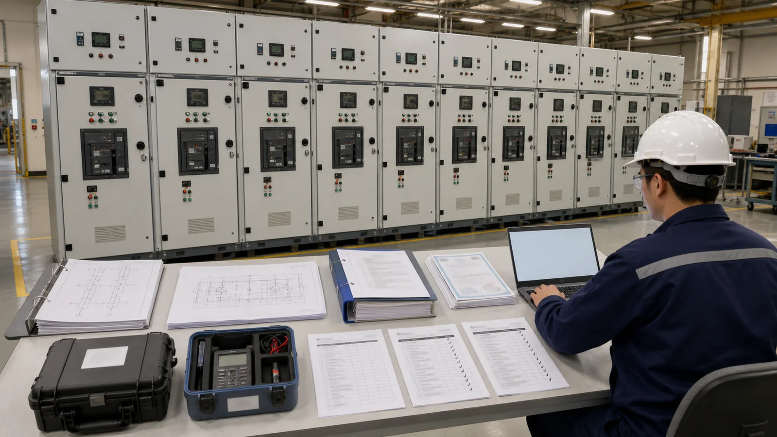
Start with the approved document set, then walk the lineup bay by bay. Confirm cabinet tags, dimensions, lineup order, voltage/current/fault-duty data, bus-section arrangement, breaker and switch models, CT/PT data, relays, meters, auxiliary voltage, cable entry, earthing interfaces, and accessories.
This stage catches the costly problem of testing the wrong configuration. On a KYN28 metal-clad switchgear lineup, the review should connect the breaker truck, relay chamber, cable compartment, grounding switch, interlock system, CT/PT arrangement, and auxiliary circuits to the approved bay schedule. Do not accept a similar component model merely because its headline rating appears suitable.
IEC 62271-200:2021 applies to prefabricated AC metal-enclosed switchgear above 1 kV and up to and including 52 kV within its public scope. It provides an equipment-standard reference, not a complete project FAT script or evidence that a particular lineup has passed.
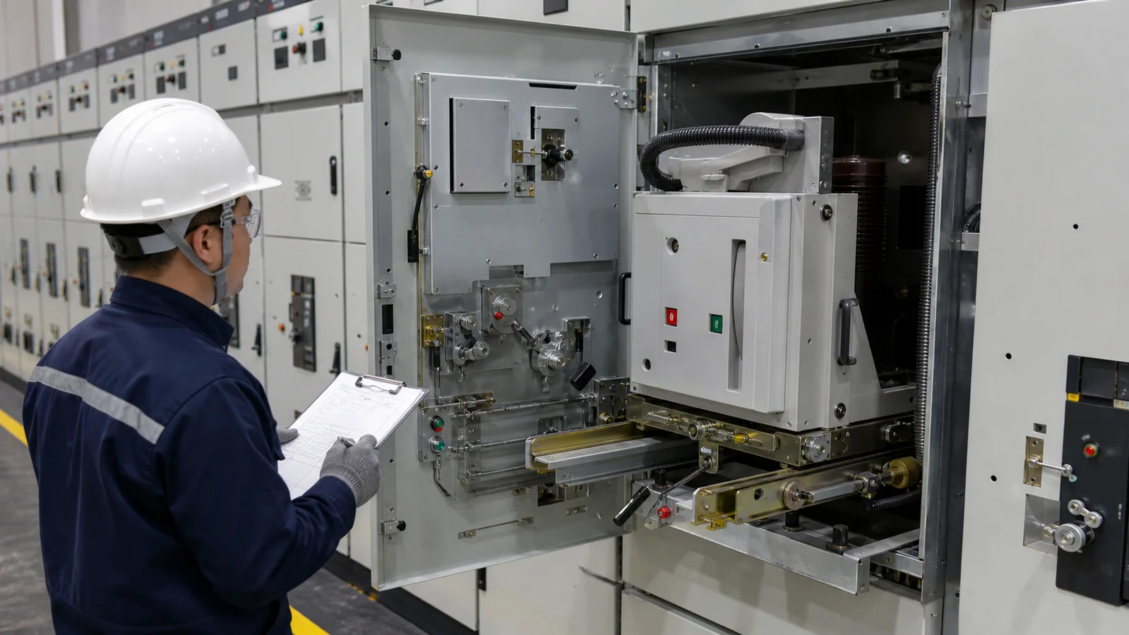
Visual inspection covers workmanship and configuration before electrical testing begins. Check enclosure condition, partitions, doors, fasteners, busbar and conductor routing, insulation surfaces, cable interfaces, earthing conductors, labels against the approved schedule, wiring support, terminal accessibility, and foreign-material control.
Mechanical checks depend on the cabinet design. For withdrawable switchgear, operate the breaker truck through the positions defined by the approved design; observe shutters, position indications, mechanical stops, door relationships, and relevant interlocks. Operate grounding switches and other mechanisms only through the specified sequence. Verify that removable devices, keys, handles, and accessories match the release list.
The witness should record what was operated and which document defined acceptance. A photograph alone does not prove an interlock sequence, and a smooth mechanism does not prove the electrical permissive logic.
Point-to-point and functional checks establish that secondary circuits match the approved schematic. The scope may include terminal numbering, wire identification, continuity, polarity, CT secondary earthing, PT circuits, fuses/MCBs, auxiliary supplies, trip and close circuits, anti-pumping logic, local/remote selection, heaters, lighting, alarms, indications, and spare terminals.
The witness should trace representative signals from their source to the final output rather than accepting only a lamp test. For example, a simulated alarm should appear at the intended relay input, local indication, gateway point, and remote point where those interfaces are included.
Any temporary test jumper must be controlled and removed. The final configuration should be compared with the released schematic before closing the stage.

Protection testing uses the approved settings and test procedure. The test may verify selected pickup, timing, logic, output contacts, trip circuit, event record, alarm, and lockout functions. It should not be used to invent or approve settings at the FAT table unless the project assigns that responsibility and controls the revision.
Electrical and mechanical interlocks are tested through the approved safe sequence. Simulated factory conditions cannot prove every site-dependent permissive. Functions involving external transformers, upstream/downstream devices, site earthing, or live network state require later site verification.
Communication checks should use the approved protocol, point list, addresses, scaling, quality flags, command permissions, and time source. A successful network connection is not enough; the correct data must reach the correct point and commands must respect the operating philosophy.
For GIS gas-insulated switchgear, project checks may also cover the selected sealed-tank configuration, density-monitoring circuits, gas alarms/lockouts where applicable, module sequence, cable interfaces, and related manufacturer procedures. Requirements depend on the chosen GIS design.
The actual tests, connections, safety controls, and limits come from the approved FAT procedure, applicable standards, product manuals, and project documents. Do not copy a value from another cabinet or use a generic internet checklist as the acceptance source.
| Activity | Tool or Evidence | Acceptance Source | Record Requirement |
|---|---|---|---|
| Insulation condition | Approved insulation test setup | Project specification, applicable procedure, and OEM manual | Test record with circuit state, result, instrument, and calibration reference |
| Main current path | Contact resistance measurement where specified | OEM manual and approved baseline/limit | Phase-by-phase result and connection/position notes |
| Protection functions | Calibrated secondary-injection equipment | Approved setting file and FAT procedure | Input, expected result, actual result, event/output evidence |
| Auxiliary/control supply | Calibrated meter and functional source | Approved schematic and project specification | Voltage, polarity, circuit state, and deviation record |
| Withstand or other routine test | Approved test equipment and safety plan | Applicable standard and released test procedure | Full test record and authorized sign-off |
| Deviation handling | Punch-list and corrective action forms | Approved concession and quality procedure | Root cause, correction, retest, evidence, and closure authority |
This is a fictional example, not a XIYA POWER or customer FAT, measured test result, real nonconformance, or shipment record.
Assume the installed relay in Bay 4 is revision B, while the approved data sheet and bill of materials reference revision A. The headline functions look similar, but the firmware menu and configuration file format differ.
The witness records the discrepancy and pauses functional tests for that bay. The manufacturer supplies the revision-B data sheet and a technical comparison. The buyer then chooses one controlled disposition: replace the relay with the approved revision, formally approve the substitution and revise the documents, or reject it. If the substitution is accepted, the revised setting/configuration file is loaded and the complete protection, output, event, and communication sequence is retested. The punch item closes only when the approved documents and retest evidence agree.
The useful pattern is observe, record, contain, investigate, approve a disposition, correct, retest, and close. Skipping document revision would leave the delivered equipment different from the handover record even if the functional check passed.
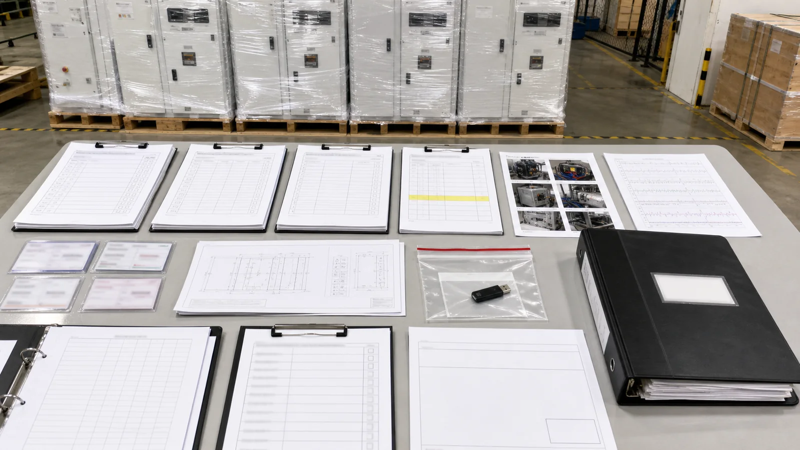
Individual passes do not automatically release the lineup. The release package should show completed test records, instrument traceability, deviations, corrective-action evidence, retests, concessions, updated drawings, final settings/configuration files where required, manuals, routine-test evidence, packing inspection, and the agreed document register.
Classify punch items by their effect on safety, function, compliance, documentation, and shipment. A critical unresolved item should block release. A minor item may remain open only when the authorized buyer accepts a written disposition, owner, due date, and closure evidence. Oral agreement is not an auditable release condition.
Buyers using an OEM/ODM manufacturing route should define the same ownership clearly: who approves drawings, supplies settings, witnesses tests, signs concessions, controls branded documents, and authorizes packing.
Before leaving the factory, confirm that every scheduled FAT step has a recorded outcome; every skipped or not-applicable item has an approved reason; calibration references were captured; test configuration was restored; temporary jumpers were removed; settings and files have revision identifiers; punch items have owners and dispositions; and the release authority signed the correct lineup and document revision.
Attendance depends on the contract and ITP. It may include manufacturer engineering and quality personnel, the buyer/EPC, consultant, owner or utility witness, and specialist relay or communication engineers. The approved witness and hold points determine who must sign.
No. FAT does not verify final cables, site earthing, room installation, external interlocks, network coordination, or energization readiness. SAT and commissioning remain separate controlled stages.
Record and contain the issue, stop affected tests, investigate the root cause, obtain an approved disposition, complete corrective action, and repeat the affected sequence plus any necessary regression checks before release.
Confirm instrument identity, calibration status, validity period, range/suitability, and traceability according to the approved quality procedure. Record the instrument reference on the corresponding test form.
No. Routine tests address production requirements for the manufactured equipment. A project FAT combines the specified routine evidence with configuration, witness, functional, document, and project-specific checks defined by the order.
A useful FAT is not a factory tour or a stack of generic certificates. It is a controlled comparison between the ordered configuration and the manufactured lineup, supported by traceable results and closed deviations. Shipment should follow only when the defined evidence, documents, punch-list dispositions, and release authority agree.



