Quotation form
Send an inquiry
Start with the basics. Our team can follow up for missing drawings, standards or packing details.
Submitted details are used only for quotation, technical review and project communication.

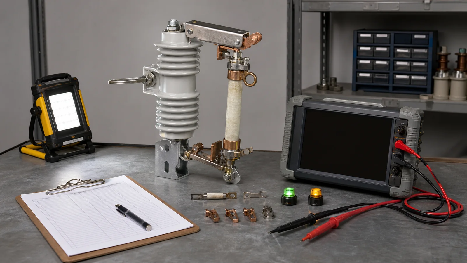
Drop out fuse inspection troubleshooting should begin with the event record and as-found condition, not immediate fuse-link replacement. Identify the installed cutout, preserve evidence, inspect each component group under the approved maintenance state, and compare every result with the model-specific manufacturer instructions and project procedure. Keep the assembly on hold until the cause, compatible parts, corrective action, and release evidence are closed.
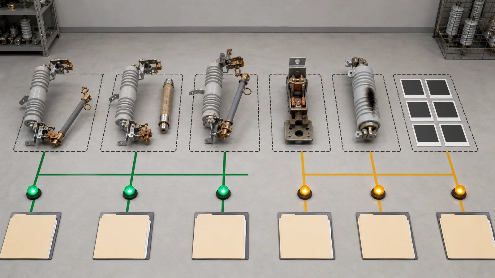
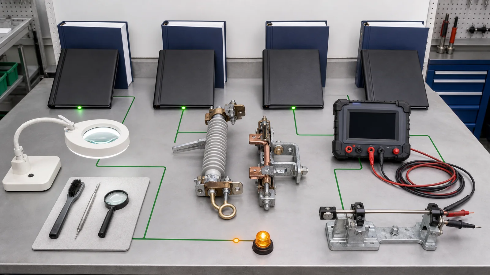
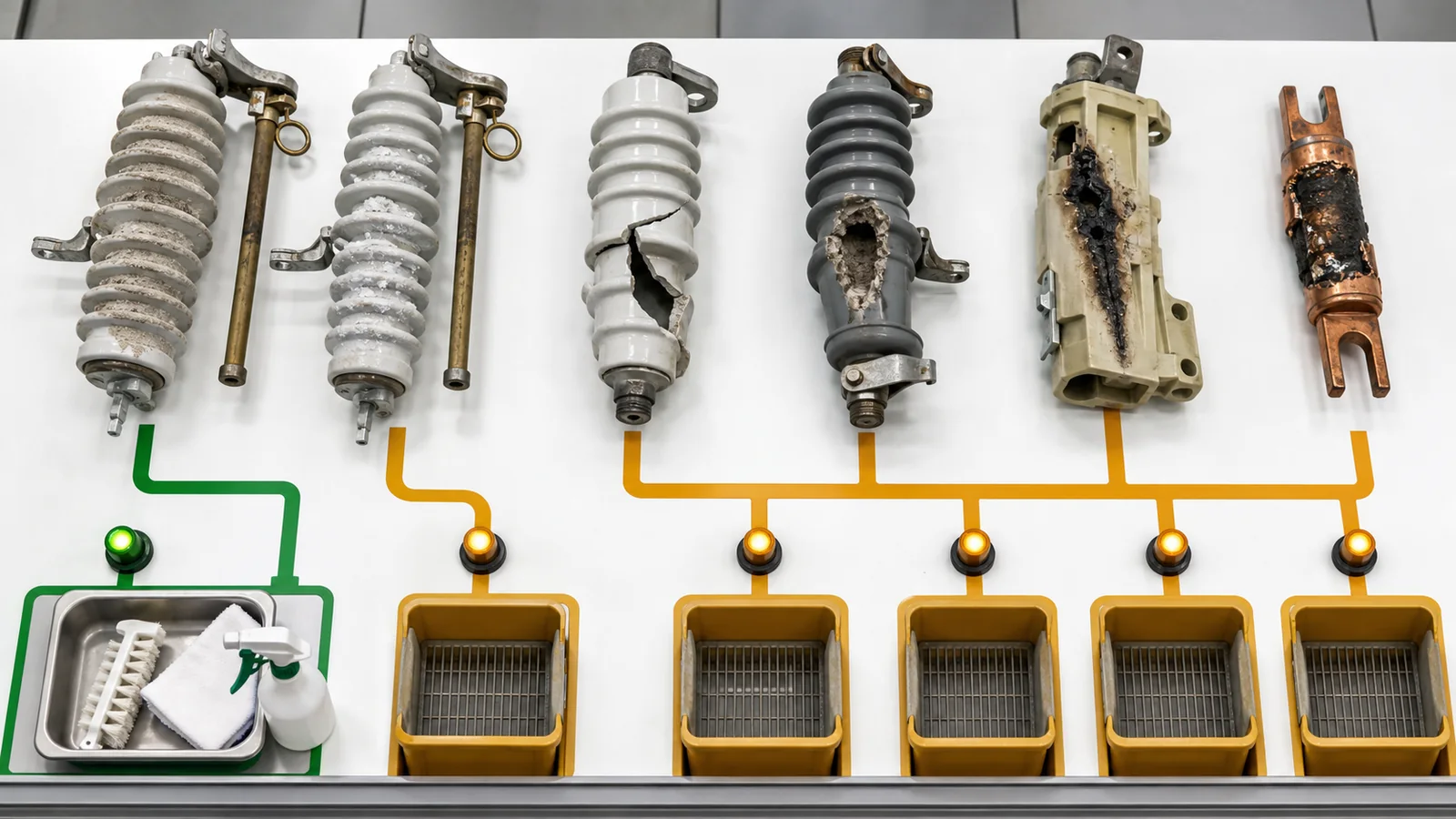
Visual disclosure: all images are generated illustrative technical visualizations, not XIYA POWER factory, customer, inspection, service, maintenance, test, FAT, manufacturing, installation, commissioning, or field photographs.
Before changing the assembly, record the cutout and fuseholder model, fuse-link identity, phase and pole location, event time, protection or outage data, weather and contamination, previous work, and as-found photographs. Note whether the holder dropped fully, remained partly engaged, or was already disturbed. A dropped holder shows that the protection assembly responded; it does not prove the initiating fault or confirm that the contacts, tube, and insulation remain serviceable.
Only qualified personnel applying the utility or site’s approved procedure determine isolation, grounding, absence-of-voltage confirmation, PPE, approach boundaries, tools, and return-to-service authority. This guide does not provide a live-work or switching sequence. Readers who need the operating principle first can review the drop-out fuse cutout foundation.
| Symptom | First test | Likely cause | Next action |
|---|---|---|---|
| Fuseholder found open | Preserve event and link evidence before removal | Fault, overload, link deterioration, or mechanical release | Investigate the circuit and inspect the full assembly |
| Holder open but link appears intact | Check link identity, latch, hinge, and seating surfaces | Wrong part, broken leader, corrosion, misalignment, or latch defect | Hold and resolve the electrical/mechanical cause |
| Holder will not seat or stay closed | Inspect contacts, latch, hinge, alignment, and link interface | Damaged contact, obstruction, incompatible part, or deformation | Do not force; isolate the defective component path |
| Contact or terminal is discolored | Review thermal evidence, then inspect de-energized interfaces | Pitting, film, loose connection, overload, or poor seating | Use the controlled inspection/test route |
| Insulator or tube has tracking marks | Inspect the complete surface and adjacent hardware | Conductive contamination, erosion, or prior flashover | Hold for source-based disposition |
| Same position operates repeatedly | Review fault, load, protection, and prior replacement records | Recurring circuit fault or unsupported link selection | Escalate to protection and equipment owners |
`
`
Treat this troubleshooting chart as a routing aid. It cannot replace the installed product manual or establish permission to operate, test, clean, close, or energize the cutout.
Build the inspection record by component and keep each finding open, conditionally closed, or closed. Where the approved procedure removes a link, holder, contact, or terminal part, retain its identity and orientation with the event record. This prevents a later replacement from erasing the connection between the as-found evidence, corrective action, and reviewed release state.
Record the link before removal. Check its complete identity, button or threaded arrangement, leader condition, small tube, attachment, and relationship to the fuseholder. Corrosion, broken strands, damaged arc-control parts, or an incorrect interface can impair operation even when the ampere marking appears plausible. A new link is corrective action only after the operating cause and replacement compatibility are resolved.
Separate three questions:
If the link curve, ampere value, tube, holder, body, or interrupting combination is uncertain, route it to the transformer fuse selection and coordination owner. Maintenance should not validate an unsupported selection by repeatedly installing the same part.
Eaton’s official Type L/LB cutout instruction is a bounded manufacturer example. Its maintenance section addresses link corrosion and deterioration, cracked or heavily contaminated insulation, contact pitting or burning, liner damage, and tracking or flashover. Those checks are useful categories, but its product-specific dimensions, ratings, and procedures are not universal. The installed model’s OEM manual and site procedure control the decision.
Inspect the complete current path rather than the most visible contact. At the upper and lower contacts, record pitting, burning, material loss, discoloration, deposits, deformation, and uneven engagement. At terminals and conductors, look for heat effects, corrosion, looseness, damaged strands, or evidence that the connection moved. At the hinge, trunnion, latch, and pull-ring structure, check for distortion, wear, obstruction, corrosion, and inconsistent seating.
Do not infer contact pressure, torque, or alignment from appearance alone. Same-model phase comparison can identify an abnormal position, but it does not create a pass/fail threshold. Any instrumented check must have a defined equipment state, method, instrument status, connection points, and acceptance source.
| Tool or check | Purpose | Required equipment state | Acceptance source | Instrument status | Required record |
|---|---|---|---|---|---|
| Detailed visual inspection | Locate damage, deposits, misalignment, and heat evidence | Approved isolated/de-energized state | OEM manual and maintenance plan | Lighting and viewing aid identified | As-found photographs and defect map |
| Contact resistance comparison | Assess the current-path interface under a controlled method | Approved de-energized and prepared state | OEM manual, project specification, or approved comparison basis | Micro-ohmmeter ID and calibration status | Leads/method, measured results, temperature, and comparison |
| Insulation surface assessment | Separate contamination from cracking, erosion, or tracking | Approved de-energized state | OEM manual and project specification | Tool/material status as applicable | Surface condition and disposition |
| Mechanical fit review | Check hinge, latch, alignment, and compatible seating | State defined by the approved procedure | Controlled drawing and OEM manual | Approved operating/inspection tool identified | Observation and corrective action |
| Electrical test, if expressly required | Support a defined insulation or continuity question | State and connections defined by procedure | Approved test plan and acceptance source | Instrument ID and calibration status | Complete test record and reviewer |
`
`
A number without method and source is not release evidence. Where no controlled criterion exists, record the result as diagnostic information and retain the hold for engineering or manufacturer disposition.
Identify the insulation material and exact drop-out fuse product family before choosing a maintenance route. Porcelain, polymer sheds, fuseholder liners, terminals, and metal contacts do not share one cleaning or damage rule. Pollution type, wetting, salt, industrial deposits, previous flashover, and material condition all matter.
Loose dry deposits on an intact surface may be cleanable when the controlled source permits the method. Wet conductive contamination, cemented deposits, or repeated pollution require investigation of the site exposure and shed condition. Cleaning does not restore cracked porcelain, torn or eroded polymer, exposed core, carbonized tracking, flashover damage, burned hardware, or lost contact material.
| As-found condition | Disposition path | Evidence before release |
|---|---|---|
| Loose deposit; surface intact | Clean only by the approved material-specific method | Before/after condition and completed reinspection |
| Heavy or wet contamination; no visible permanent damage yet | Hold, clean if permitted, then inspect the full leakage path | Method, source, photos, and post-clean disposition |
| Cracked porcelain or structural polymer damage | Replace through the controlled parts route | Correct identity, replacement record, and reinspection |
| Tracking, carbonization, flashover, or severe erosion | Hold; cleaning alone is not an acceptable closure | Engineering/manufacturer disposition and replacement evidence |
| Burned or materially pitted contact | Assess replacement/repair under the model-specific source | Component identity, method, test record, and release approval |
`
`
No universal cleaning agent, pressure, solvent, interval, resistance limit, or acceptable amount of erosion applies. If damage remains visible or the contamination mechanism is unresolved, the finding remains open.
An operated link with no dropout directs attention to the ejecting path, latch, hinge, corrosion, deformation, and obstructions. A holder that cannot seat may involve damaged upper contacts, incompatible link hardware, bent parts, deposits, or alignment loss. A holder that seats and then releases can indicate worn retention geometry, obstruction, or an incorrect holder/body combination. Stiff movement requires a controlled inspection; it is not permission to force the mechanism.
Recurring discoloration or heating requires separation of contact-film/pitting, terminal connection, seating, and load. Repeat fuse operation requires circuit-fault and protection evidence, not only another mechanical inspection. Trial closing cannot prove that the downstream fault is absent, and replacing a higher-rated link cannot substitute for coordination review.
Keep device duty in view. The broader Distribution Switching Equipment hierarchy separates fuse protection from load switching, isolation, breaker, and recloser functions. If the required operating duty has changed, maintenance should raise an engineering decision instead of modifying the cutout to perform another device’s role.
Release requires more than free movement. The record should close the event cause, exact replacement identity, contact and insulation findings, mechanical condition, applicable test results, unresolved restrictions, reviewer, and authorized release state.
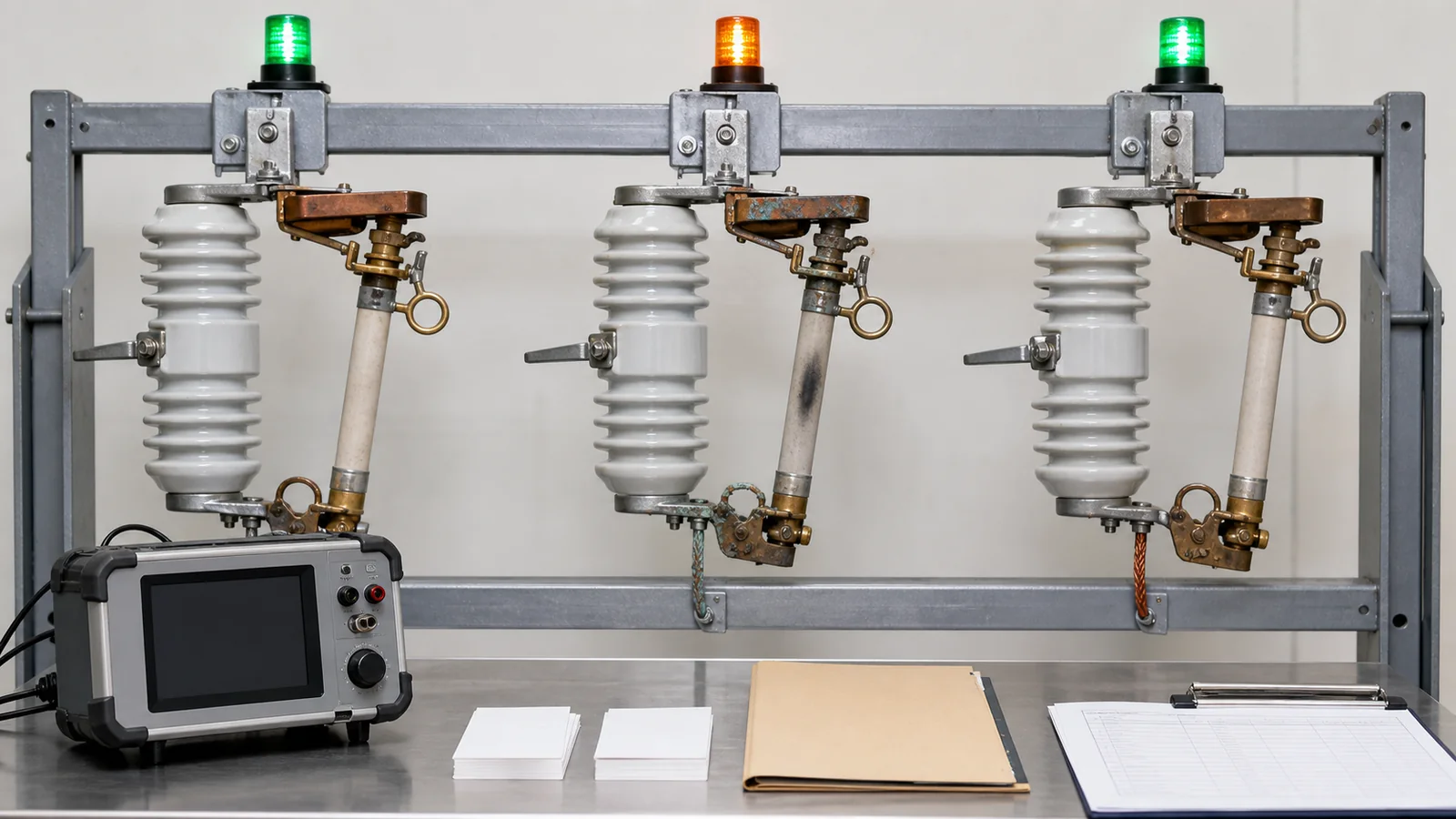
Representative diagnostic example, not a XIYA POWER customer, factory, inspection, service, maintenance, test, installation, commissioning, or field case. All identities and measured values are illustrative and non-universal.
Three adjacent same-model single-phase cutouts are reviewed under one approved de-energized method. The suspect position has an as-found upper-contact resistance of 286 micro-ohms. The adjacent positions measure 92 micro-ohms and 97 micro-ohms using the same instrument and method. The difference prioritizes the suspect contact for investigation; none of these values is a universal acceptance limit.
The suspect position also has heavy upper-contact pitting, corrosion on the fuse-link leader, and a carbonized tracking mark inside the fuseholder. Together, these findings raise separate contact, moisture/contamination, link-condition, and insulation questions. One normal dropout event does not by itself explain or close them.
`
`
Decision: hold the suspect assembly. Preserve photographs, measured data, instrument identity/status, link and holder identity, phase comparison, and event context. Investigate the operating event and interfaces; inspect the adjacent positions; and route compatible repair or replacement through the controlled manufacturer and site procedure. Require documented reinspection and named release authority. For exact replacement identification or document review, contact XIYA POWER only after the complete identity and as-found package is available. No repair success, test pass, or return-to-service outcome is claimed.
Preserve the event and as-found evidence first. Then inspect the link identity/condition, upper and lower contacts, terminals, hinge, latch, alignment, fuseholder liner, insulator surface, contamination, and applicable protection evidence under the approved maintenance state.
Not until the cause of operation and compatible replacement identity are resolved. Repeated replacement can hide a recurring fault, unsupported coordination, deteriorated link, damaged contact, or defective holder.
Possible contributors include pitting, deposits, reduced engagement, corrosion, loose/damaged terminal interfaces, incorrect seating, or excessive load. Separate these causes with source-controlled inspection and testing rather than one visual assumption.
Only when the model-specific source permits the method and the underlying surface is intact. Cracking, exposed core, severe erosion, carbonized tracking, flashover, or burned hardware requires hold and replacement/engineering disposition.
Possible causes include a stiff/corroded hinge, damaged latch, deformation, obstruction, incompatible parts, wrong link installation, or an incomplete operating mechanism. The assembly should not be forced or trial-closed to diagnose it.
Retain event data, as-found photographs, exact component identity, inspection/test methods, instrument status, results, corrective action, replacement traceability, closed findings, remaining restrictions, reviewer, and authorized release decision.



