Quotation form
Send an inquiry
Start with the basics. Our team can follow up for missing drawings, standards or packing details.
Submitted details are used only for quotation, technical review and project communication.

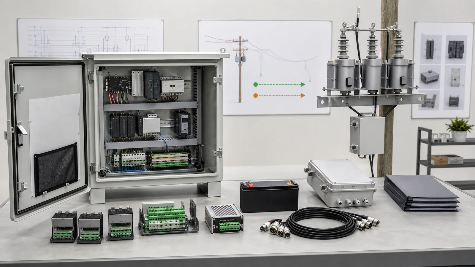
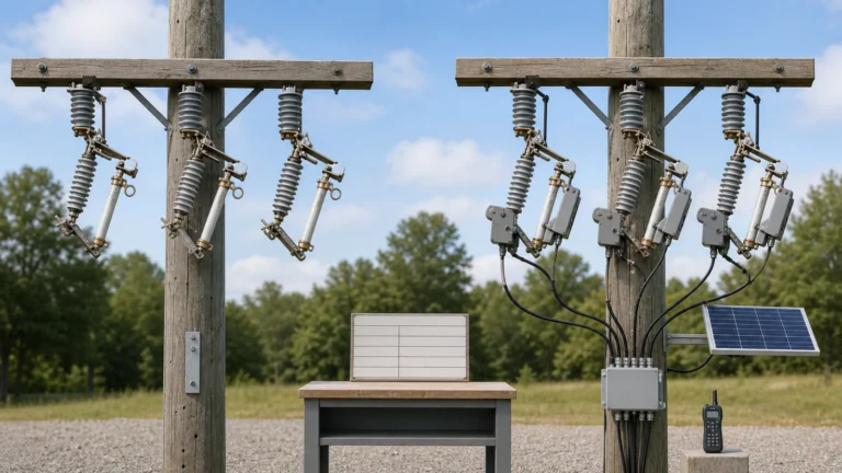
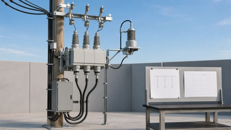
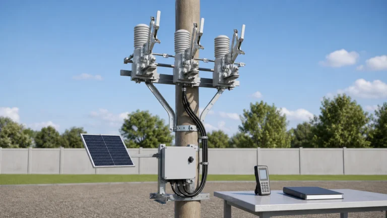
All images are generated illustrative technical visualizations, not XIYA POWER factory, design, inspection, test, FAT, manufacturing, installation, commissioning, or field photographs.
A feeder automation controller RFQ is ready for quotation only when the offered configuration maps every required interface to project-controlled evidence. The buyer must define I/O characteristics, control-power duty, communication interfaces, protection boundaries, primary-device compatibility, and enclosure conditions. A controller family name or protocol label cannot replace this data pack.
Buy the controller against an approved functional and interface boundary, not a generic catalogue description. Upstream engineering should define what the feeder must do before procurement defines how the controller will implement it.
The feeder automation design inputs article owns topology, operating states, control-power architecture, communication architecture, and point-list inputs. The switching-device role guide determines whether the primary device acts as a recloser, sectionalizer, or boundary switch. This article then specifies the controller hardware and direct interfaces. The Smart Grid product family remains the commercial owner for the package.
Start with a controller selection matrix. Each line should connect a required input to an offered value, a controlled document, a decision owner, and a release state.
| Required input | Supplier return | Release evidence | Decision | Hold condition |
|---|---|---|---|---|
| Approved functional boundary | Completed compliance matrix | Referenced project requirement and supplier document revision | Evaluate | Requirement is unanswered or conditional |
| Approved interface list | Channel and terminal mapping | I/O schedule, terminal drawing, and connector schedule | Release interface | Function lacks an electrical implementation |
| Named primary device | Compatibility declaration | Model-specific interface drawing and data | Release pairing | Controller compatibility is generic |
| Controller configuration | Exact hardware, options, and software | Configuration list with revision status | Release offer | Catalogue family is named without options |
| Engineering data pack | Drawings, datasheets, files, and tools | Revision-controlled document index | Release documents | Required record is missing or superseded |
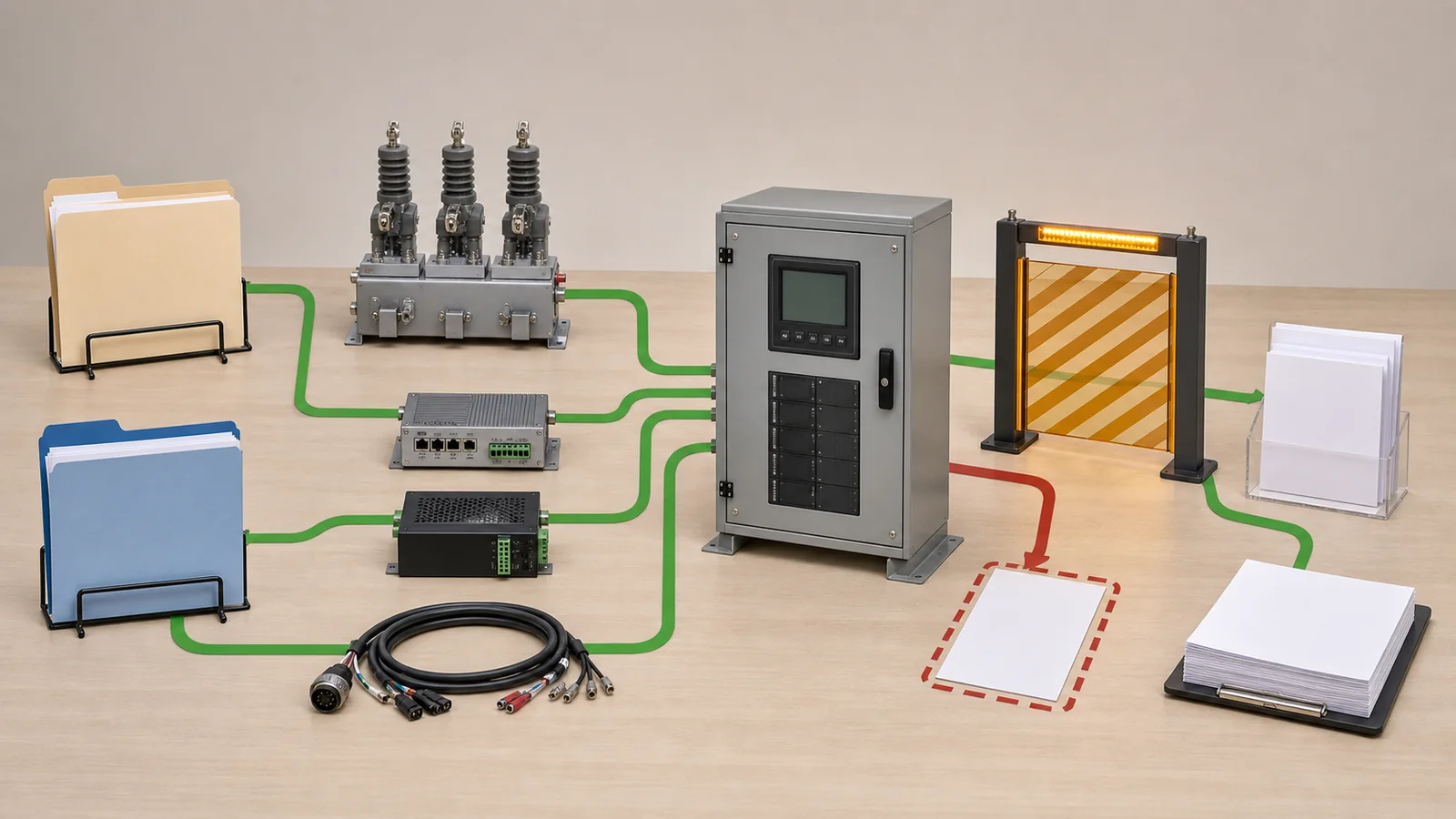
The matrix also prevents scope overlap. Controller procurement should not silently redesign feeder states, protection philosophy, or the switching-device role. Any change to those upstream decisions returns to the responsible engineer before the controller offer progresses.
Channel count is only the first I/O question. The RFQ must describe each channel’s electrical behavior and its relationship to an approved function.
For digital inputs, identify the signal source, wet or dry contact arrangement, nominal level, threshold behavior, burden, isolation, filtering, and fail state. For outputs, identify relay or solid-state construction, contact arrangement, continuous and switching duty, isolation, default state, and diagnostic feedback. Analog inputs need their quantity type, nominal range, burden, accuracy requirement, withstand duty, and sensor or transformer interface.
The buyer should also define terminal numbers, connector and pin assignments, cable ownership, shield and grounding boundary, interposing-device responsibility, permissives, and controlled spare allocation. These details belong in an I/O RFQ checklist rather than an unreferenced note in a supplier email.
| Required input | Offered value | Data pack | Technical release | Hold condition |
|---|---|---|---|---|
| Digital input characteristics | Per-channel electrical return | Datasheet and I/O map | All functions map to suitable inputs | Count is given without levels or burden |
| Output characteristics | Contact type and switching duty | Datasheet and wiring drawing | Load and fail state are compatible | Count is given without contact evidence |
| Analog or sensor interface | Type, range, burden, and accuracy | Interface schedule and datasheet | Every measured quantity maps correctly | Generic analog capability is returned |
| Isolation and grouping | Group boundary and rated evidence | Datasheet or applicable report | Required circuits are separated | “Isolated” has no stated basis |
| Physical connection | Terminal, connector, and pin mapping | Controlled terminal and cable drawings | End-to-end connection is traceable | Connector family lacks pin assignment |
| Spare philosophy | Named spare channels by electrical type | Approved marked-up I/O list | Spare allocation is controlled | Unassigned capacity is called spare |
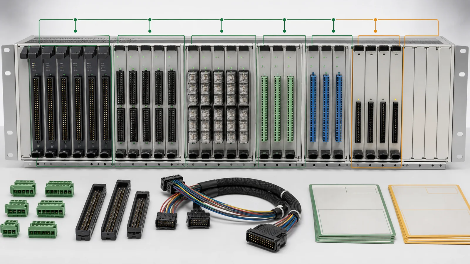
The point-list owner still controls the required functions and status meanings. The controller supplier returns the hardware implementation and declared limitations. Procurement should hold any interface that cannot be traced in both directions.
Specify the complete control-power boundary. The RFQ should name the source, nominal and allowable range, frequency where applicable, grounding method, protective devices, connectors, and the behavior expected during low or lost supply.
List every load served by that boundary. This can include the controller, communication equipment, sensors, indication, enclosure heater or cooling, charger, and primary-device trip or close circuits. The approved project architecture determines which loads belong in the calculation. Do not assume that the controller datasheet represents the full cabinet burden.
Where stored energy or backup autonomy is required, request the battery technology, capacity basis, charger characteristics, alarm returns, environmental derating basis, and autonomy calculation. The calculation should use the approved load schedule and the project’s operating sequence. It should separate continuous, intermittent, peak, and inrush duties.
| Required input | Supplier return | Release evidence | Hold condition |
|---|---|---|---|
| Supply source and allowable conditions | Exact input range and connection | Datasheet and power drawing | Project source compatibility is not declared |
| Complete auxiliary-load schedule | Load by device and operating state | Referenced burden calculation | A modem, heater, sensor, or actuator is omitted |
| Backup or autonomy duty | Capacity and calculation basis | Battery and charger data plus calculation | Charger data is returned without autonomy evidence |
| Protection and grounding | Device, rating, location, and bonding | Wiring and earthing drawings | Protection is unnamed or not coordinated with the boundary |
| Degraded behavior | Alarms, retained functions, and blocked functions | Functional statement or approved logic description | Low-supply behavior is undefined |
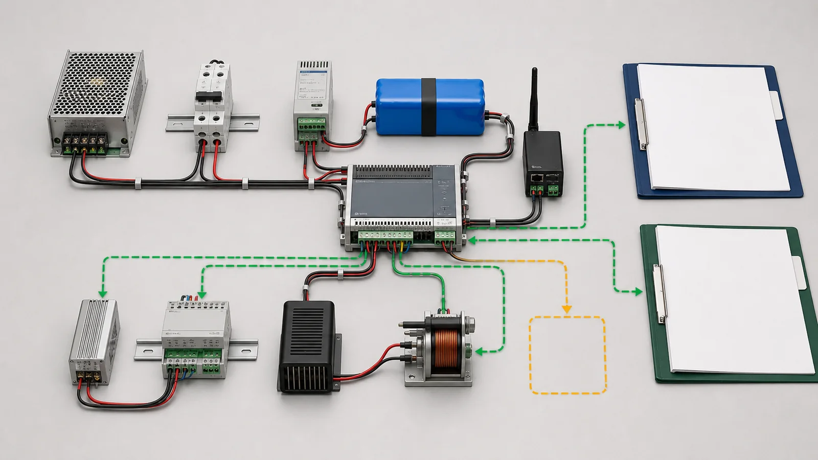
The release question is not whether a charger is present. It is whether the returned source, total burden, storage basis, alarms, and degraded behavior satisfy the project requirement as one system.
A protocol name does not define a usable communication interface. Each connection needs a physical medium, connector, port quantity, isolation boundary, protocol version or profile, operating role, addressing responsibility, and gateway boundary.
The supplier return should identify the project mapping deliverable, time-synchronization source, event and oscillography capability, record retrieval method, configuration backup, firmware basis, and engineering access. It should also name required software, licenses, cables, supported operating environment, user roles, and controlled credential handover. Cybersecurity requirements should reference the project’s approved policy instead of improvised article guidance.
Protection and automation need a separate responsibility line. The RFQ may request required functions, usable measured quantities, logic capacity, setting-file format, event records, and test evidence. Project protection settings, automation logic, and release authority remain engineering responsibilities. Controller capability cannot correct an unsuitable primary device.
Controlled evidence sources may include manufacturer data, the project specification, and the approved short-circuit study or TCC when they define required protection capability. These sources define the procurement boundary; they do not authorize settings.
The official Eaton Form 6 recloser control page provides a bounded manufacturer example. It shows that one named control can have different mounting configurations, identifiable ports and connections, access controls, and stated equipment compatibility. Those product-specific details do not define this RFQ. They demonstrate why a buyer must request the exact offered configuration and evidence rather than a family name.
The controller must map to the selected primary device by model and interface revision. The automatic vacuum circuit recloser page provides product context. The automatic recloser RFQ checklist owns the complete recloser package, while this article owns the controller-only return.
Request trip and close circuit characteristics, auxiliary-contact behavior, sensor and transformer interfaces, cable and connector pinouts, interposing devices, permissives, interlocks, and a named compatibility declaration. A statement that the controller is “suitable for reclosers” is not enough.
The enclosure schedule should freeze mounting, access, material, coating, ingress duty, operating environment, altitude, condensation control, solar exposure, and thermal controls. It should also define cable entry, gland plate, earthing, locking, labels, clearances, dimensions, and mass. Requirements come from project conditions, not a universal template.
Require a completed compliance matrix as the supplier’s formal return. Every line should state the offered value, source document, revision, declared deviation, and release status. Brochures may support the return, but they should not replace project-tagged evidence.
Before technical release, check four relationships together:
Any broken relationship stays on hold. Procurement should not turn an undocumented assumption into an accepted deviation.
Representative engineering review, not a XIYA POWER customer, factory, design, inspection, test, FAT, manufacturing, installation, commissioning, maintenance, or field case. All quantities, electrical values, channel counts, protocol details, ingress ratings, temperature ranges, and findings are illustrative and non-universal.
The review covers one pole-mounted feeder controller for a previously selected three-phase automatic recloser. The required control source is 230 VAC nominal with an internal 24 VDC battery subsystem and eight hours of autonomy.
The approved interface list calls for 16 digital inputs, eight relay outputs, four 1 A current inputs, and four 110 V voltage inputs. Communication requires two Ethernet ports, one RS-485 port, an IEC 60870-5-104 project profile, and SNTP time synchronization. The required enclosure is IP55 over an ambient range of -25 C to +55 C.
| Required input | Observed return | Decision | Required record | Hold condition |
|---|---|---|---|---|
| 230 VAC source, 24 VDC battery, eight-hour autonomy | 110-240 VAC input and charger named | Hold | Complete load and autonomy calculation | Combined controller, modem, heater, actuator, and battery duty is absent |
| 16 digital inputs and eight relay outputs | Headline counts match | Hold | Per-channel levels, burden, contact type, switching duty, and isolation | Electrical I/O characteristics are absent |
| Four 1 A current and four 110 V voltage inputs | Analog channels are not separately returned | Hold | Input type, burden, accuracy, withstand, and terminal mapping | No analog-interface evidence |
| Two Ethernet and one RS-485 port | One Ethernet port is offered | Hold | Hardware configuration and port drawing | Required interface capacity is missing |
| IEC 60870-5-104 profile and SNTP | Protocol name only | Hold | Project profile, mapping, addressing, role, and time statement | Protocol and time evidence are incomplete |
| IP55, -25 C to +55 C | IP54, -20 C to +50 C | Hold | Compliant enclosure and environmental return | Offered boundaries do not meet the illustrative requirement |
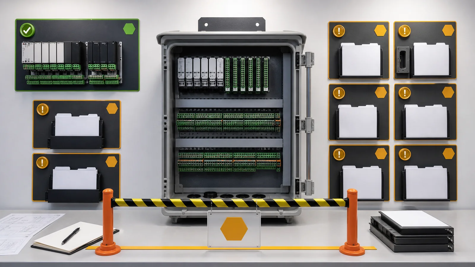
The offer remains on technical hold. Required records include the complete load and autonomy schedule, electrical I/O characteristics, analog-interface evidence, and the required port configuration. Communication profile, time, enclosure, and environmental evidence must also close.
Matching headline channel counts does not close these gaps. No supplier award, factory test, installation, commissioning, operating result, or final disposition is claimed or implied.
It should include the approved function and interface boundary, electrical I/O, control-power duty, communication profile, protection responsibility, primary-device interface, and enclosure conditions. Software dependencies, documents, deviations, and release evidence must also be defined.
Specify each channel by function, electrical type, nominal range, threshold or switching duty, burden, isolation, fail state, connector, terminal, mapping, and required evidence. A channel count alone is insufficient.
No. The RFQ also needs media, connector, ports, version or profile, role, addressing ownership, mapping return, time synchronization, security boundary, engineering access, and test evidence.
The project’s authorized protection and automation engineers should define and approve them. The supplier should return controller capability, file formats, limitations, event records, and the agreed implementation evidence.
The return should cover mounting, access, material, coating, ingress evidence, environmental range, condensation and thermal controls, cable entry, earthing, locking, labels, clearances, dimensions, mass, and document revisions.
Hold it whenever a required interface, burden, compatibility statement, communication profile, enclosure condition, document reference, revision, or declared deviation is missing, conditional, or incompatible with the project requirement.