Quotation form
Send an inquiry
Start with the basics. Our team can follow up for missing drawings, standards or packing details.
Submitted details are used only for quotation, technical review and project communication.

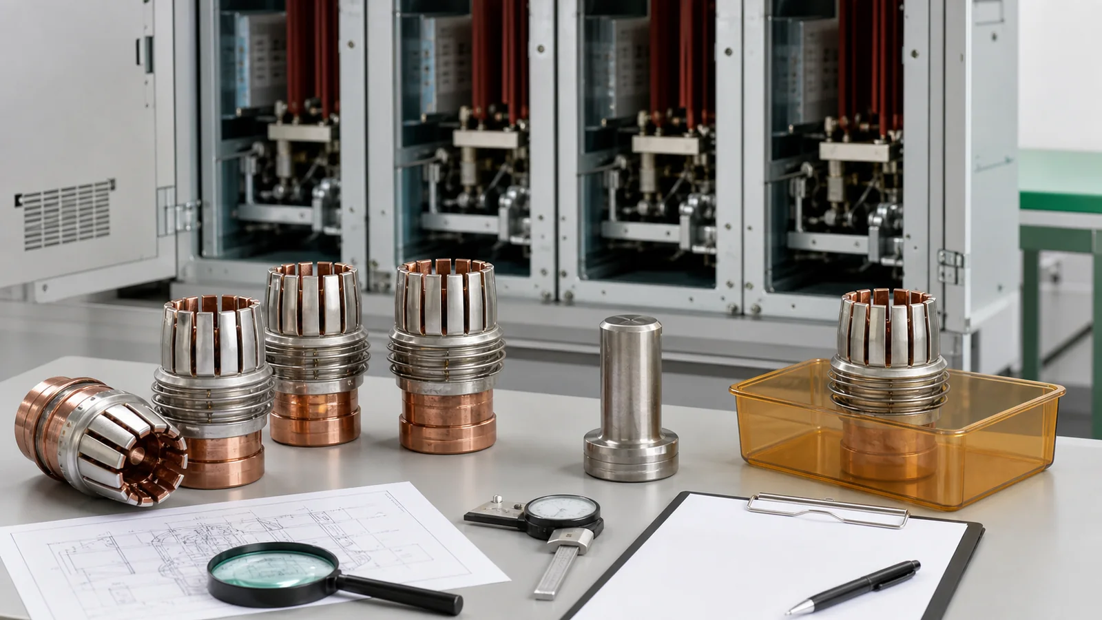
A switchgear contact assembly inspection should release a part only when its identity, mechanical condition, pressure evidence, installed alignment, plating condition, and records all agree with an approved acceptance source. A clean appearance, matching label, hand-pressure check, or single resistance reading is not enough. The inspector must verify the assembly and its mating interface as one controlled current-path connection.
Fixed, tulip, and flat contacts use different geometries, but the release logic is consistent: match the controlled part and revision, inspect fingers and spring hardware, verify pressure or engagement by the specified method, check the installed witness pattern, and close every deviation before release.
Inspection starts with documents, not the package. The acceptance source may be an approved drawing and revision, product or assembly specification, inspection procedure, project requirement, or formally approved deviation. A value remembered from another cabinet or copied from an uncontrolled supplier sheet is not a release criterion.
Use the Switchgear Components pillar to confirm the cabinet zone and component family, then apply the switchgear component acceptance checklist to the specific contact assembly.
| Required record | What it controls | Hold condition |
|---|---|---|
| Purchase line and revision | Identity, quantity, and ordered scope | Missing, superseded, or mismatched record |
| Part drawing and revision | Geometry, orientation, material, and interface | Uncontrolled or wrong revision |
| Cabinet/breaker position | Line/load side and installed reference | Position or orientation is ambiguous |
| Batch or lot record | Traceability and inspection scope | Mixed or unidentified lot |
| Material/plating requirement | Coating identity and acceptance basis | Requirement is absent or unlinked |
| Inspection plan | Method, sampling, tools, and records | Method or scope is not approved |
| Deviation register | Conditional acceptance or rework | Open disposition affects the item |
The record should also identify the mating arm or spigot, applicable fixture, instrument status, and who can approve rework. Missing inputs are resolved before inspection proceeds; they are not recorded later as administrative notes after the part has already been accepted.
Assemble those sources into one inspection packet before the item reaches the bench. The packet should show which manufacturer drawing or data sheet is controlled by the purchase record, which project specification adds requirements, which inspection plan defines coverage, and which test record closes each applicable check. It should also separate supplier-provided evidence from checks performed after installation. This prevents a coating certificate from being treated as an installed-interface result, or a cabinet-level record from being assigned to a loose replacement contact without an applicability review. The inspector should be able to trace every release cell to one named source and revision.
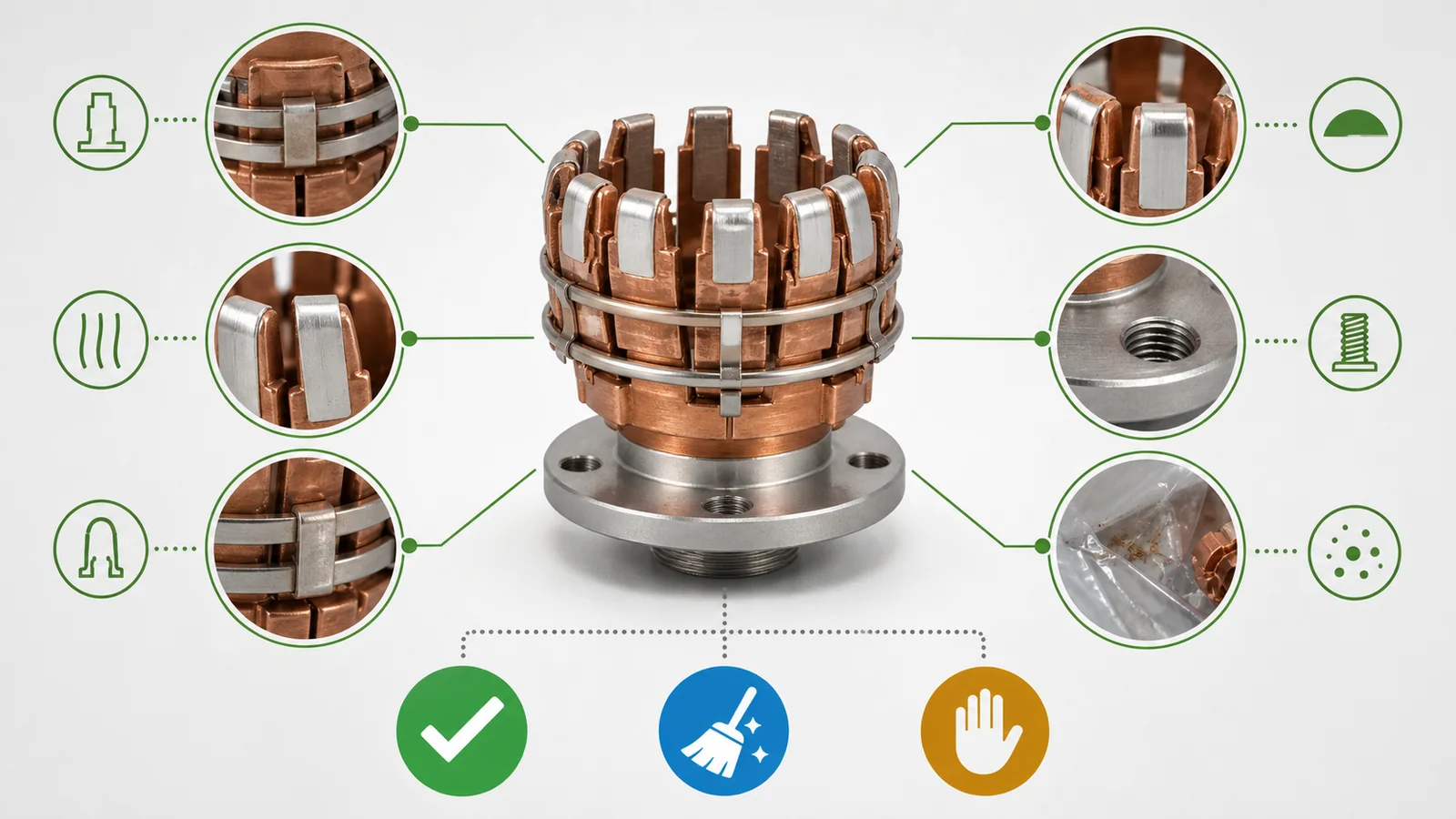
Record package damage, moisture, contamination, or impact evidence before handling changes the condition. Then verify the part ID, revision mark, orientation, lot, and required hardware against the controlled record. Finger count is useful only as a drawing-match attribute; it does not prove pressure, geometry, or current-carrying capability.
| Inspection area | Look for | Initial disposition |
|---|---|---|
| Package and cleanliness | Moisture, debris, packing fragments, residue, corrosion | Record; clean only by an approved method; reinspect |
| Contact fingers | Bending, spreading, dents, burrs, edge damage, unequal openings | Hold for assessment or approved rework |
| Springs and clips | Missing, loose, damaged, or displaced bands and retainers | Hold until disposition and reinspection |
| Mounting interface | Damaged threads, distorted seats, missing hardware, wrong orientation | Hold against drawing and assembly record |
| Contact surfaces | Gouges, coating damage, foreign particles, exposed substrate | Record and classify against the approved criterion |
Use three practical states. Record and clean applies when an approved cleaning method can remove contamination without changing the surface. Rework and reinspect requires an approved operation and a repeat check against the original criterion. Quarantine pending disposition applies when damage, missing hardware, deformation, or an unclassified surface condition prevents release. A defect does not by itself prove electrical failure, but it does stop acceptance until its effect and disposition are controlled.
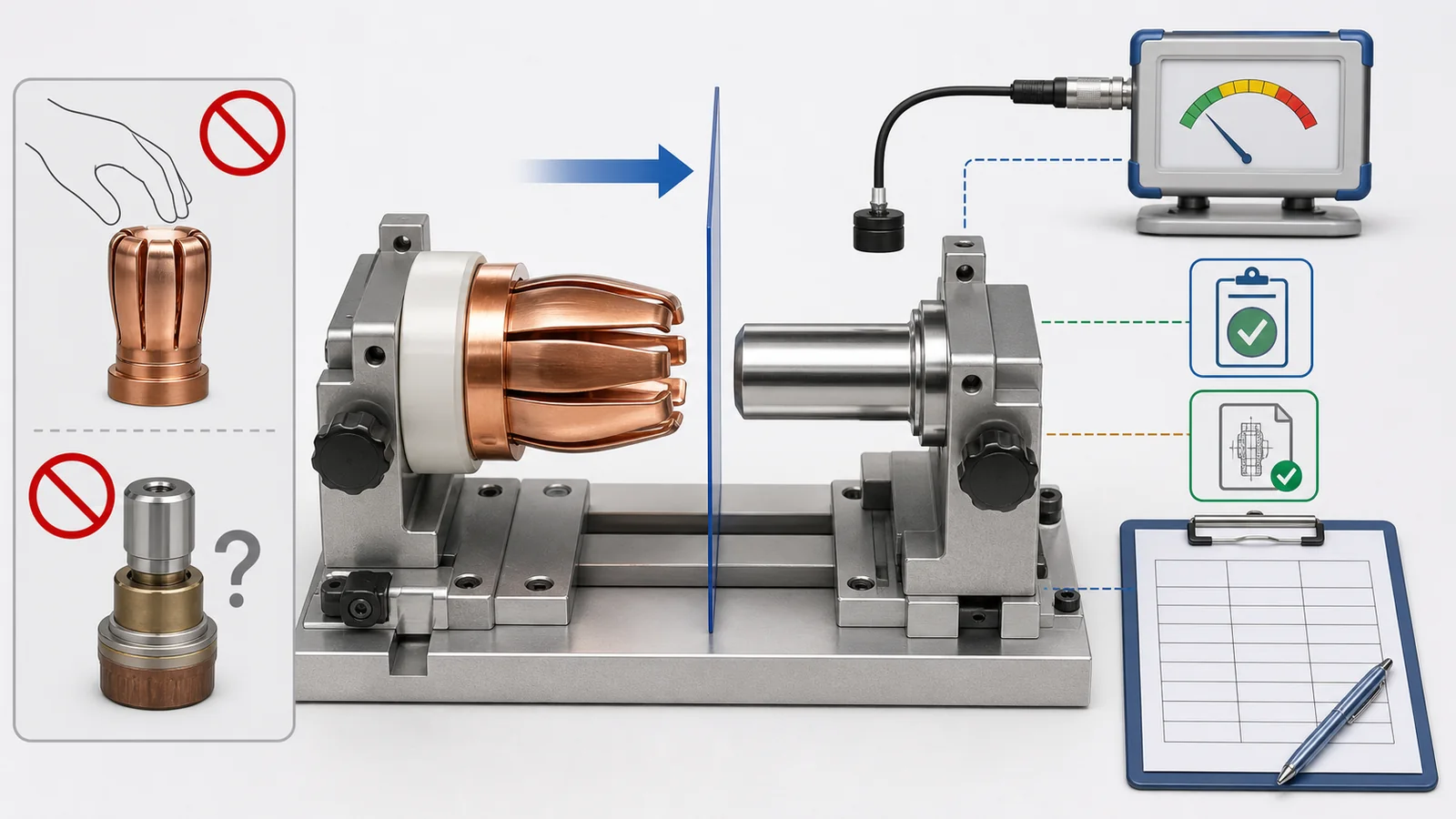
Touch is not a pressure test. Visual spring compression, hand feel, or comparison with an unverified sample produces no traceable result and cannot be repeated against the same criterion. The approved pressure or engagement method must define the fixture or gauge, force direction, engagement reference, assembly-level or individual-finger criterion, inspection scope, acceptance band, and record format.
| Evidence element | Required control | Inadequate substitute |
|---|---|---|
| Instrument or fixture | Identified, suitable range, current status | Hand feel or an unknown sample |
| Test movement | Defined direction and method | Arbitrary push/pull action |
| Engagement reference | Drawing- or procedure-defined position | Estimated insertion depth |
| Acceptance source | Approved drawing, procedure, or specification | Memory or another project value |
| Inspection scope | Approved sample or complete-lot rule | One convenient assembly |
| Result record | Item/lot, method, tool, revision, result, disposition | Verbal confirmation |
An acceptable loose-assembly check does not prove installed alignment. Conversely, an abnormal installed engagement result does not prove that the contact alone is defective. Mating geometry, mounting position, contact-box location, and drawout travel can change the load distribution. The record must therefore distinguish a component check from an installed-interface check.
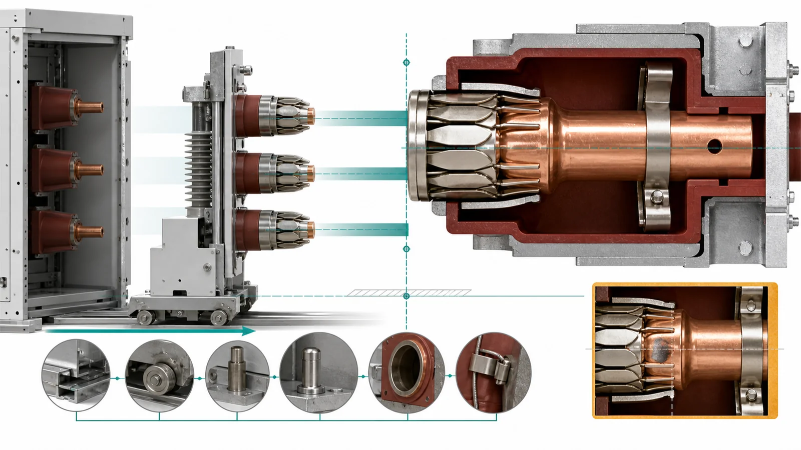
Installed acceptance checks centerline, concentricity, approach direction, engagement position, finger opening, spring retention, and phase-to-phase consistency against the approved assembly reference. The mating arm or spigot should enter without visible side loading, and the contact trace or witness pattern should be reasonably distributed according to the specified inspection method.
The contact, copper arm, contact-box interface, mounting structure, and drawout truck form one mechanical chain. An asymmetric witness pattern can originate from the contact, the mating part, a centerline offset, the truck approach, or the service-position stop. COMP-02 verifies this already selected assembly; dimensional replacement matching remains a separate decision.
| Observation | Possible interface | Required check | Release state |
|---|---|---|---|
| Asymmetric witness pattern | Side load or centerline offset | Arm/spigot position and mounting alignment | Hold pending investigation |
| Partial engagement | Approach or position reference | Truck travel and approved engagement reference | Hold pending check |
| Spring shifts during engagement | Spring seat, finger geometry, or side load | Condition before/after engagement; approved rework | Hold pending disposition |
| One phase differs from the others | Position-specific or common mounting variation | Compare all positions to one controlled reference | Hold affected set |
| Consistent engagement and retained springs | Interface follows approved reference | Record evidence and close checks | Eligible for release |
Service-position confirmation completes the check for a drawout arrangement. It should establish that the truck reaches the approved position and that engagement does not displace the assembly. Do not force a mechanism to make the witness pattern look acceptable.
Plating identity comes from the drawing, material requirement, or linked coating certificate, not color alone. Inspect required contact areas for coverage, peeling, blistering, flaking, exposed substrate, deep scratches, dents, contamination, oxidation, and residue. Classify every finding against the approved source; where that source does not define the condition, hold it for engineering disposition rather than creating a universal cosmetic rule.
Improvised abrasives or aggressive polishing are not acceptance methods. They can remove coating, alter the contact surface, and hide the original condition. Cleaning and rework need an approved method followed by reinspection.
Contact-resistance data is supporting evidence only when the procedure, instrument, connection points, acceptance source, and tested current path are defined. A loose component result is not the same as the complete installed path through the mating interface and connected conductors. Do not use one reading to overrule damaged hardware, poor alignment, or unresolved plating evidence.
Keep the evidence hierarchy explicit. A coating certificate supports the supplied material or process record; it does not prove that every delivered contact surface is undamaged. A loose-part inspection confirms the component condition at that stage; it does not prove the final cabinet interface. An installed-path result can support the assembled connection, but only within its approved method and measurement boundary. Relevant design or temperature-rise evidence applies to the arrangement it represents and should not be transferred to a changed contact, mating part, mounting geometry, or conductor joint without an approved applicability review. Each record answers a different acceptance question.
The public scope of IEC 62271-1 covers common specifications for AC high-voltage switchgear and controlgear above 1,000 V, while its revision summary discusses temperature-rise treatment. That context does not provide a universal component force, coating thickness, or resistance limit. The project must identify the adopted standards and the component/assembly acceptance sources that actually govern the offered design.
Representative engineering review, not a XIYA POWER customer project.
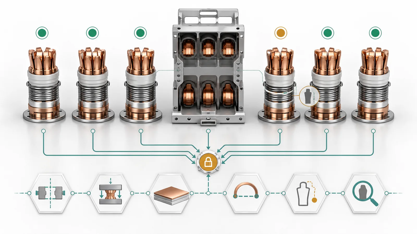
Consider one three-phase drawout-breaker set with six primary contact positions: line and load sides for each phase. All six are tulip assemblies. Five show the expected identity, finger condition, spring retention, and plating condition. One line-side assembly has a displaced spring band and an asymmetric engagement witness pattern. Its package record contains no separate approved disposition.
The affected assembly is held. The review also checks the full set because the witness pattern may reflect a common interface issue rather than only one component:
| Release item | Required action | Set-level decision |
|---|---|---|
| Spring condition | Assess the shifted band; approve rework or replacement; reinspect | Affected position remains held |
| Alignment | Verify mounting centerline, contact-box position, mating parts, and truck approach | Close for all six positions |
| Pressure evidence | Confirm method, tool status, criterion, drawing revision, and item traceability | Close the common record |
| Plating evidence | Match coating requirement and inspection record to all six items | Hold any unclassified condition |
| Installed current path | Identify the applicable acceptance procedure and record boundary | Do not substitute a loose-part result |
| Deviation closure | Record disposition, rework, and repeat inspection | Release only after closure |
This example preserves the useful decision: do not release the suspect position, but do not assume that replacing one tulip automatically resolves the interface. Close the spring, alignment, pressure, plating, installed-path, and deviation records as one set-level package.
For an inspection or RFQ review, send clear part and installed-position photos, the approved drawing/revision, mating-interface information, pressure or engagement criteria, material/plating evidence, quantity, and current deviations through the XIYA POWER contact page. Technical fit and release remain subject to the supplied documents and project requirements.
Check the controlled identity and revision, receiving condition, finger geometry, springs/clips, plating and surfaces, pressure or engagement evidence, installed alignment, witness pattern, mating interfaces, electrical evidence, deviations, and reinspection record.
No. Hand feel has no controlled direction, reference, acceptance band, instrument status, or traceable result. Use the method and criterion specified by the approved drawing, procedure, or assembly requirement.
No universal conclusion is valid. Record the location and condition, then classify it against the approved coating and surface criterion. If the criterion does not address it, hold the item for disposition rather than polishing or accepting it informally.
No. It can support release only within an approved procedure and defined current-path boundary. Identity, mechanical condition, pressure evidence, alignment, plating, and open deviations still require separate closure.
Use the purchase line, controlled part drawing, position/orientation record, batch or lot traceability, material/plating requirement, inspection plan, applicable acceptance procedure, tool status, result records, and any deviation/rework/reinspection documents.
Hold it when identity or revision is unresolved; fingers, springs, threads, or coating are damaged or unclassified; pressure/engagement evidence is missing or uncontrolled; installed alignment is inconsistent; tool status is invalid; or an applicable deviation has not been closed.