Quotation form
Send an inquiry
Start with the basics. Our team can follow up for missing drawings, standards or packing details.
Submitted details are used only for quotation, technical review and project communication.

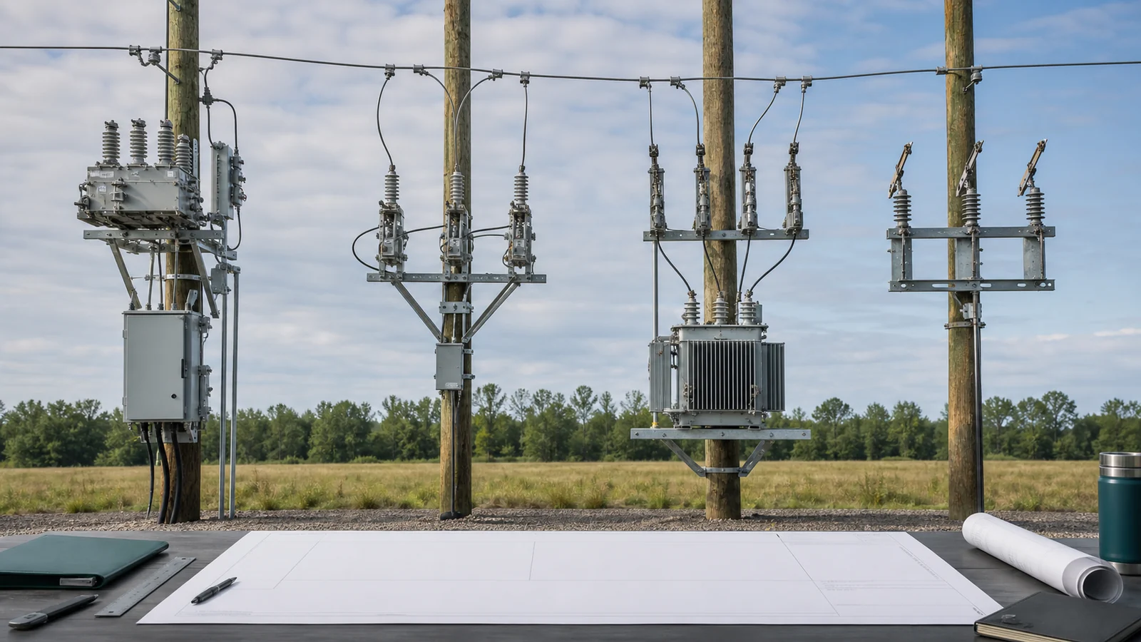
A distribution feeder equipment selection matrix should begin with the duty at each feeder position, not a preferred product name. Separate isolation, normal-load switching, overcurrent protection, fault interruption, automatic reclosing, control, and maintenance needs before comparing equipment.
The Distribution Switching Equipment pillar maps the commercial families, while the distribution switchgear foundation explains the basic duties. This article converts those foundations into a release method for source, mid-feeder, branch, boundary, and maintenance positions.
Start with the controlled one-line, feeder topology, position and normal state. Then define the required switching action, available fault basis, protection zone, isolation arrangement, operating philosophy, service conditions, and physical interfaces. A product label entered before those inputs are resolved is an assumption, not a decision.
| Feeder position or task | Required action | Candidate function | Disqualifying gap | Required input and release evidence | Hold condition |
|---|---|---|---|---|---|
| Source position | Normal switching, fault interruption, protection and isolation interface | Breaker or recloser function with a defined isolation arrangement | Interrupting or isolation duty is unproven | One-line, fault study, protection basis, declared functions and drawings | Fault or isolation basis is incomplete |
| Mid-feeder or tie | Sectionalize, make/break stated load, possibly interrupt faults or automate restoration | Load-switching or recloser function according to the duty map | Normal switching is confused with fault clearing | Normal state, load flow, fault zones, operating and reclose philosophy | Topology or required action is unresolved |
| Branch or transformer tap | Coordinate overcurrent protection and provide the required switching/isolation interface | Fuse, switch-fuse, breaker or recloser function as applicable | Protection is selected without fault and coordination data | Fault basis, equipment withstand, fuse/relay curves and coordination study | Selectivity or interrupting suitability is unproven |
| Boundary or sectionalizing point | Define responsibility, switching, protection, metering and isolation interfaces | One device or a coordinated assembly | Ownership boundary is treated as an electrical duty | Interconnection requirements, one-line, interfaces and approved operating basis | Required functions have no responsible device |
| Maintenance isolation point | Establish defined isolation and earthing access after interruption | Disconnector or declared isolating function | Open appearance is treated as proof of a safe work condition | Isolation/earthing drawing, indication, interlocks and site procedure | Isolation arrangement is not approved |
Compare offers against one matrix. A missing required input keeps the position on hold; it should not be replaced by a catalog default or by data from another configuration.
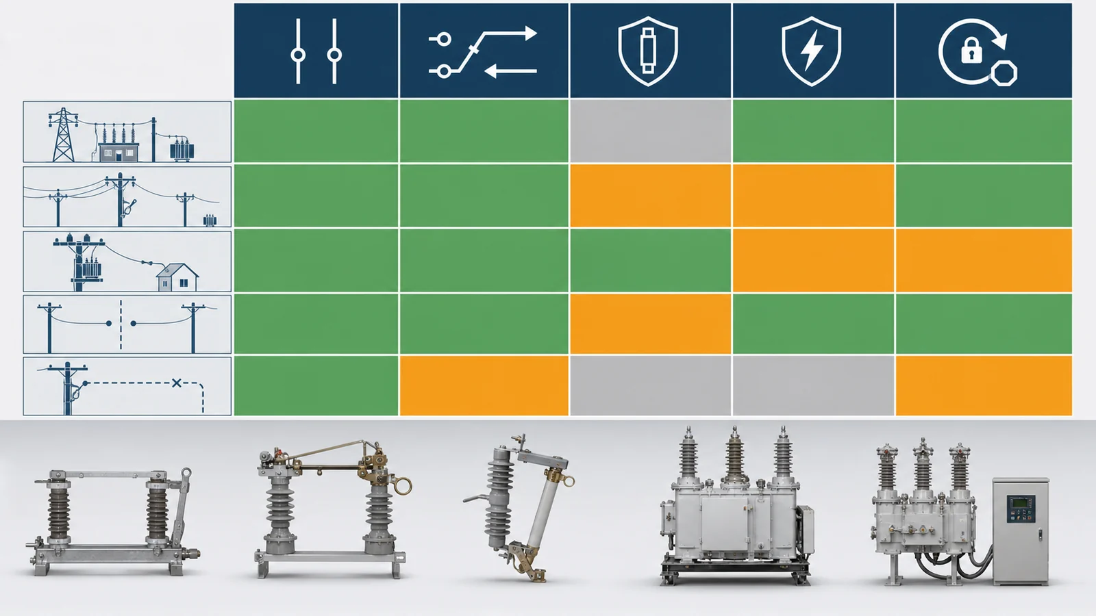
The disconnect switch versus load break switch guide owns the detailed two-device boundary. For this matrix, the practical distinction is shorter: a disconnector establishes a defined isolation point after current has been interrupted by a suitable device, while a load break switch performs its declared normal-current making and breaking duty.
Neither name proves the complete feeder function. A disconnector may have only the limited switching capabilities specifically declared for its design. A load break switch does not automatically provide fault interruption or the isolation arrangement required by the project. Motor drives, arc horns, interrupter-looking parts, controller cabinets, and visible gaps are inspection clues, not substitutes for applicable ratings and evidence.
For every proposed position, record:
Do not derive a universal operating sequence from a generic article. The project specification, equipment instructions, protection design, and site safety rules control the actual sequence.
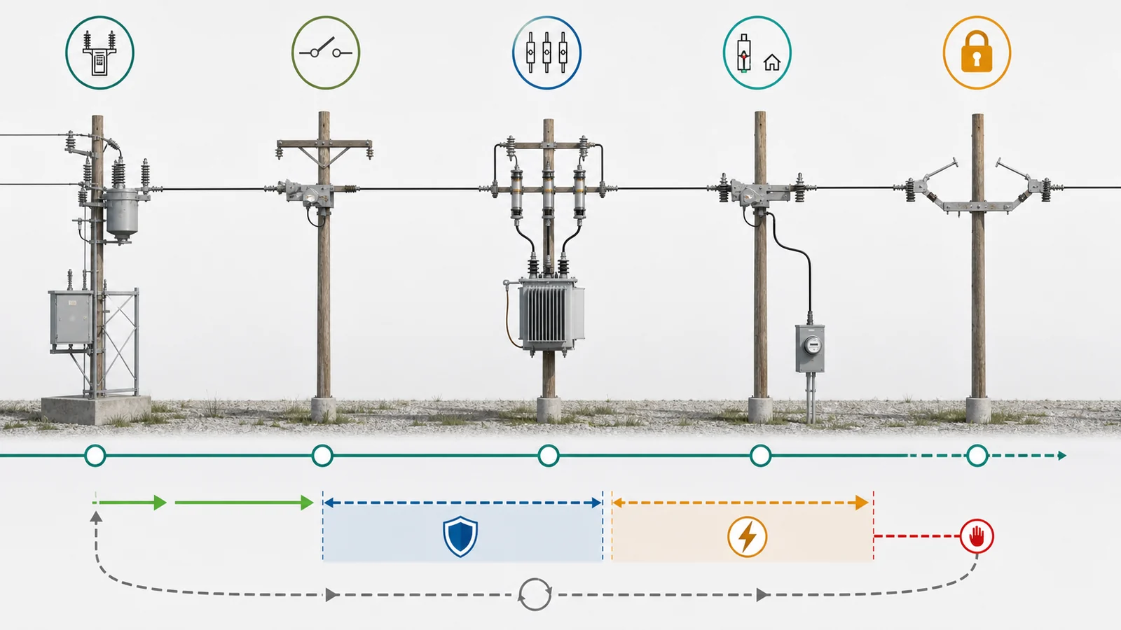
A drop-out fuse cutout can provide coordinated overcurrent protection for an applicable branch or transformer duty. Its fuse link, complete cutout interrupting capability, upstream/downstream coordination, and equipment withstand must be checked together. Fuse operation does not provide automatic reclosing, and a drop-open indication does not replace the approved isolation and absence-of-voltage process.
A circuit breaker provides the declared making and fault-breaking functions of its complete equipment package. Protection relays, sensing, control power, reclosing logic, communication, and isolation interfaces remain separate specification items unless the offered assembly explicitly includes and evidences them.
An automatic recloser combines an interrupting device with sensing, controller logic, and reclose/lockout behavior. The public IEC 62271-111:2019 page applies to specified AC automatic circuit reclosers above 1,000 V and up to and including 38 kV in overhead, pad-mounted, dry-vault, and submersible arrangements; it excludes devices requiring dependent manual operation. That public scope does not govern every fuse, switch, disconnector, or circuit breaker in this matrix.
| Function | Possible equipment route | What it does not prove automatically | Evidence needed for the position |
|---|---|---|---|
| Coordinated fuse protection | Fuse cutout or declared switch-fuse assembly | Automatic restoration, remote control, or universal isolation | Available fault basis, fuse/withstand data and coordination study |
| Resettable fault interruption | Circuit breaker package | Protection settings, reclose logic, communication, or isolation | Declared ratings, relay/sensing basis, drawings and applicable evidence |
| Fault interruption plus automatic reclose | Complete recloser package | Suitability for every source, load, transformer, backfeed, or work practice | Fault zones, reclose/lockout philosophy, coordination and control evidence |
| Normal load switching | Declared load break switch function | Arbitrary short-circuit interruption | Making/breaking data and identified fault-clearing arrangement |
Automatic reclosing is a protection-system decision. Backfeed, distributed sources, non-reclosing loads, equipment withstand, worker-safety controls, and restoration policy can change whether it is permitted. The project protection coordination study should supply the settings and timing; this system matrix should not invent them.
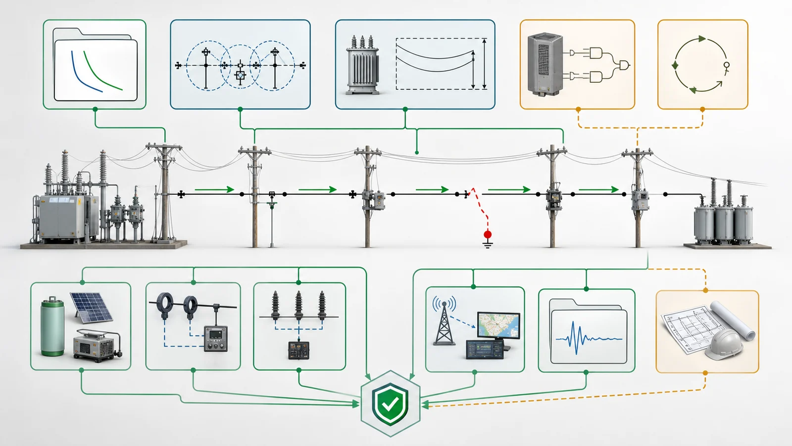
The same equipment class can fit one position and fail another. A radial feeder, ring/tie arrangement, multiple-source network, or feeder with distributed generation can change current direction, protection zones, normal state, and restoration logic. Treat topology as a controlled input rather than assuming a universal device hierarchy.
Operation and control also need their own line items. Confirm local and remote commands, automatic functions, control-power source, sensing, SCADA or DMS interfaces, time synchronization, event records, cybersecurity requirements where applicable, and the behavior expected when communication or auxiliary power is unavailable. Automation hardware cannot authorize a switching or protection duty that the complete assembly is not rated and configured to perform.
Physical and maintenance fit remains part of the decision. Review mounting, terminals, structures, conductor or cable interfaces, clearances, environment, access, indication visibility, operating mechanism, earthing points, lifting/removal space, and future extension. An electrically suitable device is not releasable if its interfaces or maintenance envelope cannot be verified at the selected position.
Future automation may justify spare I/O, sensing, communication provisions, or a documented upgrade path. It should not be used to claim that an unequipped device already provides protection, remote operation, or reclosing.
Issue one shared project basis to all bidders, then require a configuration-specific return for each feeder position.
Shared project basis:
Per-position and per-offer return:
Keep manufacturer data, the project specification, the protection coordination study, and the operating philosophy as distinct evidence sources. One cannot silently replace another. Detailed fuse-topology comparison belongs to DSE-11, while detailed load break switch rating selection belongs to DSE-12.
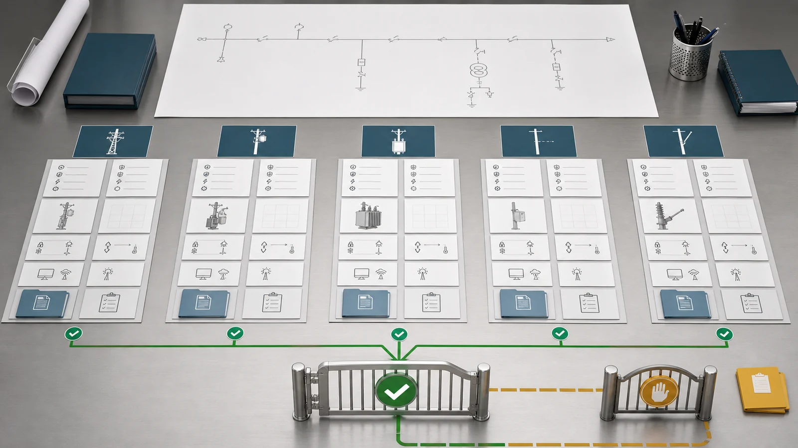
Representative engineering review, not a XIYA POWER customer project, utility case, factory case, field record, commissioned feeder, reliability result, or service result.
A radial overhead feeder has a source position, a normally closed mid-feeder point, a transformer lateral, a maintenance isolation point, and downstream loads with different continuity and reclosing constraints. An initial schedule assigns a breaker/recloser route at the source, a recloser at the mid-feeder point, a fuse cutout at the lateral, and a disconnector at the maintenance point before the controlled inputs are aligned.
The source and mid-feeder fault zones are not final. The fuse and upstream protection have no approved coordination record. The reclose philosophy does not yet separate permitted restoration from non-reclosing loads or possible backfeed. The maintenance point has no reconciled interruption, indication, earthing, and access package. Product names therefore create apparent completeness without proving the duty allocation.
Decision: hold final device allocation. Reconcile:
No voltage, current, fault level, setting, supplier, location, price, test, outage, or reliability outcome is assigned. A project-specific review should begin with the controlled feeder one-line, duty map, fault and coordination basis, operating philosophy, service conditions, and offered equipment evidence.
Only when the specific device has a declared switching capability covering that duty. A basic isolation function should not be treated as permission to interrupt normal load or fault current. Identify the suitable interrupting device and approved sequence from the project design and equipment evidence.
Compare them when a branch or transformer position needs overcurrent protection and the project must decide between fuse-based clearing with manual restoration and an interrupting/controller package with approved reclose or lockout behavior. Fault level, equipment withstand, coordination, continuity policy, backfeed, control, and maintenance all affect the decision.
Not automatically. It performs only the making and breaking duties declared for the complete device. Fault clearing may require upstream protection or a tested switch-fuse or other interrupting assembly. Verify the offered configuration rather than inferring capability from the product name.
The feeder may include non-reclosing loads, backfeed or distributed sources, equipment with constrained repeated-fault withstand, or operating and worker-safety rules requiring manual restoration. The protection study and approved operating philosophy must determine whether reclosing is permitted and how lockout is handled.
Yes, a complete assembly may declare multiple functions. Release it only when the applicable ratings, interlocks, indication, isolation arrangement, protection/control configuration, and evidence cover every required function at that position. Do not add together capabilities from unrelated variants or individual components.
Provide the feeder one-line and topology, position and normal state, system and load basis, available fault current, protection zones and coordination, reclose/lockout philosophy, isolation and earthing plan, service conditions, physical interfaces, control power, sensing, communication, applicable standards, and configuration-specific manufacturer evidence.