Quotation form
Send an inquiry
Start with the basics. Our team can follow up for missing drawings, standards or packing details.
Submitted details are used only for quotation, technical review and project communication.

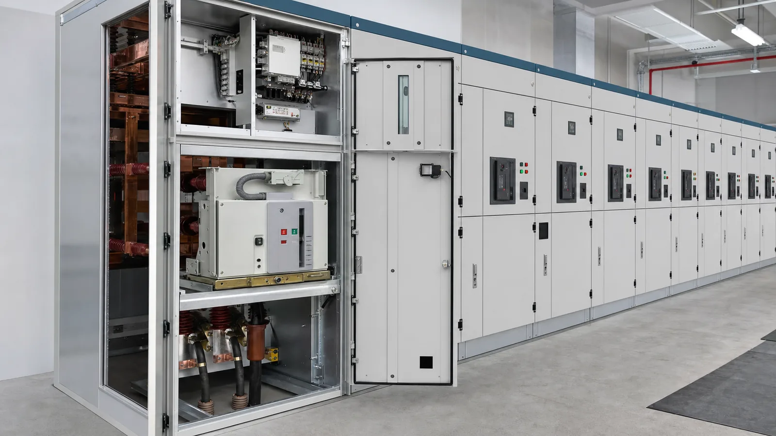
A KYN28 switchgear specification is complete only when the project one-line and panel schedule are tied to exact assembly ratings, compartments and classifications, withdrawable-device interfaces, protection and control functions, cable and room interfaces, and configuration-specific evidence. A family name, product photograph, or catalogue maximum cannot release a lineup.
The practical task is to convert system studies and installation constraints into a panel-by-panel schedule. That schedule then controls the offer, drawings, applicable evidence, deviations, and final release decision.
Start with the approved one-line, not the KYN28 type code. The Complete Switchgear Cabinets pillar establishes the portfolio context, while the MV switchgear RFQ data guide owns the upstream system inputs. This KYN28-specific stage must assign those inputs to every functional unit.
| Decision layer | Required input | KYN28 deliverable | Release evidence | Hold condition |
|---|---|---|---|---|
| Panel function | Incomer, feeder, bus-section, metering/VT and spare duties | Panel schedule by type and quantity | Approved one-line | Function or normal state is unclear |
| Bus arrangement | Sections, coupler and normal/alternate states | Bus and panel topology | Controlled switching basis | Transfer state is undefined |
| Electrical duty | Voltage, frequency, insulation, load and fault studies | Rating schedule by assembly and device | Study references | Catalogue values replace project data |
| Classification | Project accessibility and continuity requirements | Declared compartment, partition, LSC and IAC schedule where required | Applicable evidence list | Classification is inferred from KYN28 |
| Secondary system | Protection, metering, control and communication philosophy | Component and wiring schedules | Approved functions and interfaces | Ratios, functions or supplies remain open |
| Physical interfaces | Cables, trench, room, access and exhaust constraints | Interface drawings | Coordinated dimensions | Cable or room data is missing |
Record service conditions such as altitude, ambient range, humidity, pollution exposure, seismic requirements where applicable, and indoor environmental conditions. They may affect insulation coordination, thermal performance, accessories, enclosure choices, and the applicability of evidence. A spare panel also needs a defined future function and interface basis; an empty bay is not a complete spare specification.
Normalize supplier returns against this same panel schedule. One offer may state lineup-wide ratings while another assigns data by functional unit; convert both into the project’s rows before comparing them. Mark each value as a project requirement, supplier declaration, study result, or unresolved assumption. This prevents an attractive headline rating from hiding a different feeder duty, missing classification, or uncoordinated cable interface.

The KYN28 metal-clad switchgear owner page shows a product-family offer range. Treat those values as capability context, not project selections. The schedule should separate:
The official page for IEC 62271-200:2021 describes its public scope as prefabricated AC metal-enclosed switchgear and controlgear above 1 kV through 52 kV, up to 60 Hz, for indoor or outdoor service. Its public change summary also identifies clarified LSC descriptions and internal-arc test topics. The project still has to state the adopted edition, amendment status, required classifications, and evidence applicability. The public catalogue page does not supply project acceptance criteria.
Do not collapse assembly duty and breaker duty into one fault-current value. Busbars, joints, supports, branch conductors, VCBs, earthing paths, and other primary components must be coordinated with the duties that actually reach them. Incomer, coupler, feeder, metering, transformer, motor, capacitor, and spare panels can have different functional requirements even within one lineup.
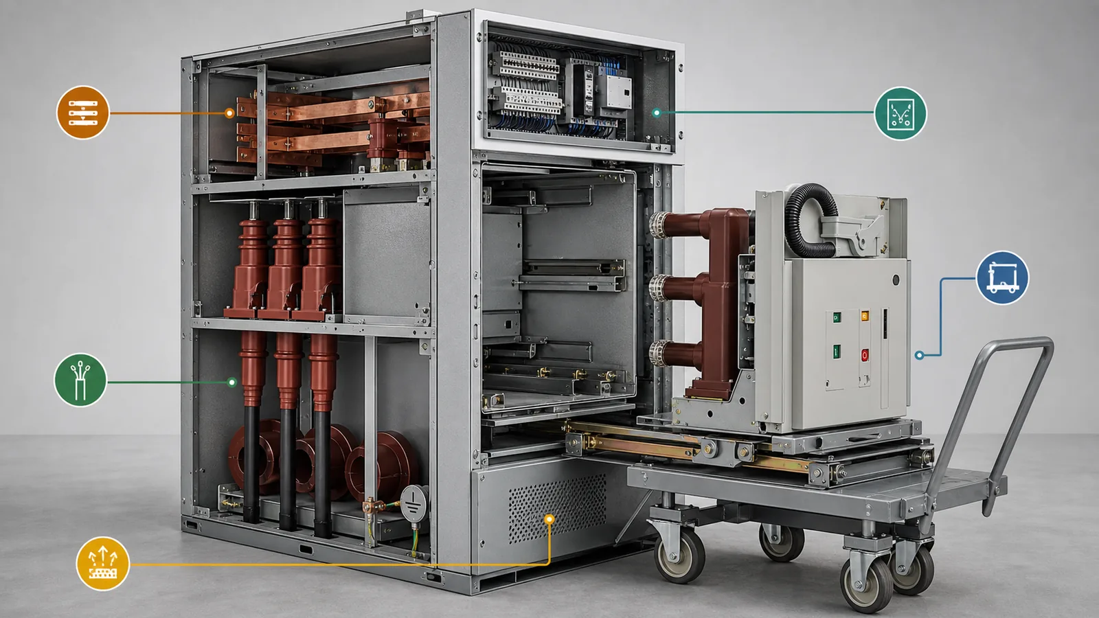
The KYN28 switchgear primer explains the basic architecture. A project specification must go further and declare the exact offered arrangement and interfaces.
| Area | Project review |
|---|---|
| Busbar compartment | Bus rating, sectionalization, joints, supports, partitions and extension interface |
| Breaker/truck compartment | Device type, truck positions offered, shutters, racking, secondary plug, indication and access |
| Cable compartment | Cable terminations, CT/VT or surge-device locations where used, earthing switch, screens and working space |
| LV compartment | Relay, metering, controls, terminal blocks, communication and LV cable entry |
| Pressure-relief path | Relief location, exhaust direction, duct or room boundary and evidence applicability |
For every truck position offered, define the primary-circuit state, secondary-plug state, shutter state, permitted operations, indication, and access boundary. Do not assume that terms such as connected, test, isolated, or removed have closed every project interface. The supplier’s drawings and operating instructions must show how the offered arrangement implements them.
If the project requires loss-of-service-continuity, partition, or internal-arc classification, place the exact declaration in the schedule and identify evidence that applies to the offered configuration. The KYN28 or KYN28A-12 name alone does not establish a classification, accessibility category, exhaust arrangement, or room suitability.
“Five-anti” is a product label, not a project interlock matrix. Define each required interlock by the hazardous or prohibited state, sensing point, mechanical, electrical, or key boundary, command authority, response to lost or contradictory information, indication, and verification method. This keeps the requirement functional without pretending that every KYN28 design uses the same sequence or hardware.
| Interface | Questions the schedule must answer | Release evidence |
|---|---|---|
| VCB and truck | Which device and truck states permit closing, opening or movement? | State diagram and approved mechanism drawings |
| Earthing switch | Which primary and access states permit operation? | Interlock matrix and operating sequence |
| Shutters and cable access | What drives or restrains them, and how is state indicated? | Compartment drawings and functional verification scope |
| Local/remote authority | Who owns a command in each selector and control condition? | Control philosophy and secondary schematic |
| Control-power loss | Which functions remain available, blocked or alarmed? | Cause-and-effect or functional matrix |
| Status evidence | Which device, truck, earth and door states are reported? | I/O, terminal and indication schedules |
Build the secondary package from the approved protection and control philosophy. It may include the VCB and auxiliary contacts, CTs, VTs, relays, meters, trip and close circuits, supervision, indication, communication, terminal blocks, and panel wiring. Ratios, accuracy requirements, burdens, relay functions, settings, protocol, control voltage, and contact quantities are project inputs or approved offer data. They must not be invented from the cabinet family.
Keep protection evidence separate from interlock evidence. A protection relay trips for defined electrical conditions; an interlock controls permissible equipment states and actions. They can exchange signals, but one does not replace the other.

A technically correct rating schedule can still produce an unusable cabinet if physical interfaces remain open. Use the following as a KYN28 RFQ checklist and close every item before technical release and drawing approval:
Do not assume that bottom entry means the actual cable set will fit. Cabinet depth, gland-plate area, termination height, accessory locations, bend envelope, installation access, and trench position have to be checked together. Likewise, an internal-arc declaration cannot be separated from the offered relief direction and the building boundary.
The RMU project specification guide shows why each cabinet family needs its own interface package. It is a sibling specification boundary, not permission to transfer RMU feeder, cable-switch, fuse, or compartment logic into KYN28.
Release evidence should be indexed, not merely attached. For each scheduled requirement, identify the governing project document, manufacturer data, supplier return, drawing, applicable verification record, and deviation. Keep the project specification, short-circuit study, and manufacturer data as distinct evidence sources. A report for another current rating, compartment arrangement, or relief configuration may be informative without proving the offered lineup. Applicability must be reviewed explicitly.

Representative engineering review, not a XIYA POWER customer, utility, factory, FAT, site, commissioning, outage, or service case. All values are illustrative and non-universal.
Consider a 12 kV indoor lineup of 10 panels across two bus sections: two 1250 A incomers, one 1250 A bus-section/coupler, six 630 A outgoing feeders, and one metering/VT panel. The illustrative main bus is 1250 A, the short-time basis is 25 kA for 3 seconds, the trip, close, and control supply is 110 V DC, the breakers are withdrawable VCBs, and cable entry is from the bottom.
Those numbers describe a panel schedule, not a released design. Hold the lineup until the normal and alternate one-line states and the coupler duty are approved; maximum and minimum fault and load studies confirm the basis; VCB, CT, VT, relay, metering, and auxiliary requirements close; compartment and classification declarations are accepted; the interlock matrix is agreed; and applicable evidence is mapped to the offered configuration.
Physical release also remains on hold until the incomer and feeder cable count, size, termination, gland plate, working envelope, screen earth, and trench are coordinated. The room must close access, truck handling, foundation, shipping splits, and any relief route. Finally, the drawing list, test and verification scope, component schedules, deviation register, and 110 V DC auxiliary-load basis must be complete.
No cable size, relay setting, cabinet dimension, test result, or operating outcome is implied by this example. Its value is the visible hold logic: a credible set of ratings does not compensate for missing interfaces.
Provide the one-line and panel schedule, system and service conditions, load and fault studies, assembly and device ratings, classifications where required, protection and control functions, interlock matrix, cable and room interfaces, drawing list, applicable evidence, and deviations.
No. It identifies a cabinet family and general architecture. Project voltage, insulation, current, fault duty, VCB duty, classifications, cable capacity, controls, and accessories must be selected and verified for the exact lineup.
Review the busbar, breaker/truck, cable, and LV relay/control areas, plus their partitions, shutters, access boundaries, pressure-relief path, earthing, and interfaces. Confirm the exact offered arrangement rather than relying on a generic diagram.
No. Approval needs a project interlock matrix defining prohibited states, sensing, boundary type, command authority, degraded behavior, indication, and verification for the offered configuration.
State cable voltage, conductor and insulation, quantity per phase, size, termination, entry, glands, cleats, bend and working envelope, screen earthing, accessory locations, and trench or foundation opening. Coordinate these inputs against the actual cable compartment drawing.
Require a marked one-line, panel and rating schedule, general arrangement, compartment and truck details, bus and cable drawings, secondary schematics, interlock matrix, terminal schedule, evidence references, routine-verification scope, and itemized deviations.