Quotation form
Send an inquiry
Start with the basics. Our team can follow up for missing drawings, standards or packing details.
Submitted details are used only for quotation, technical review and project communication.

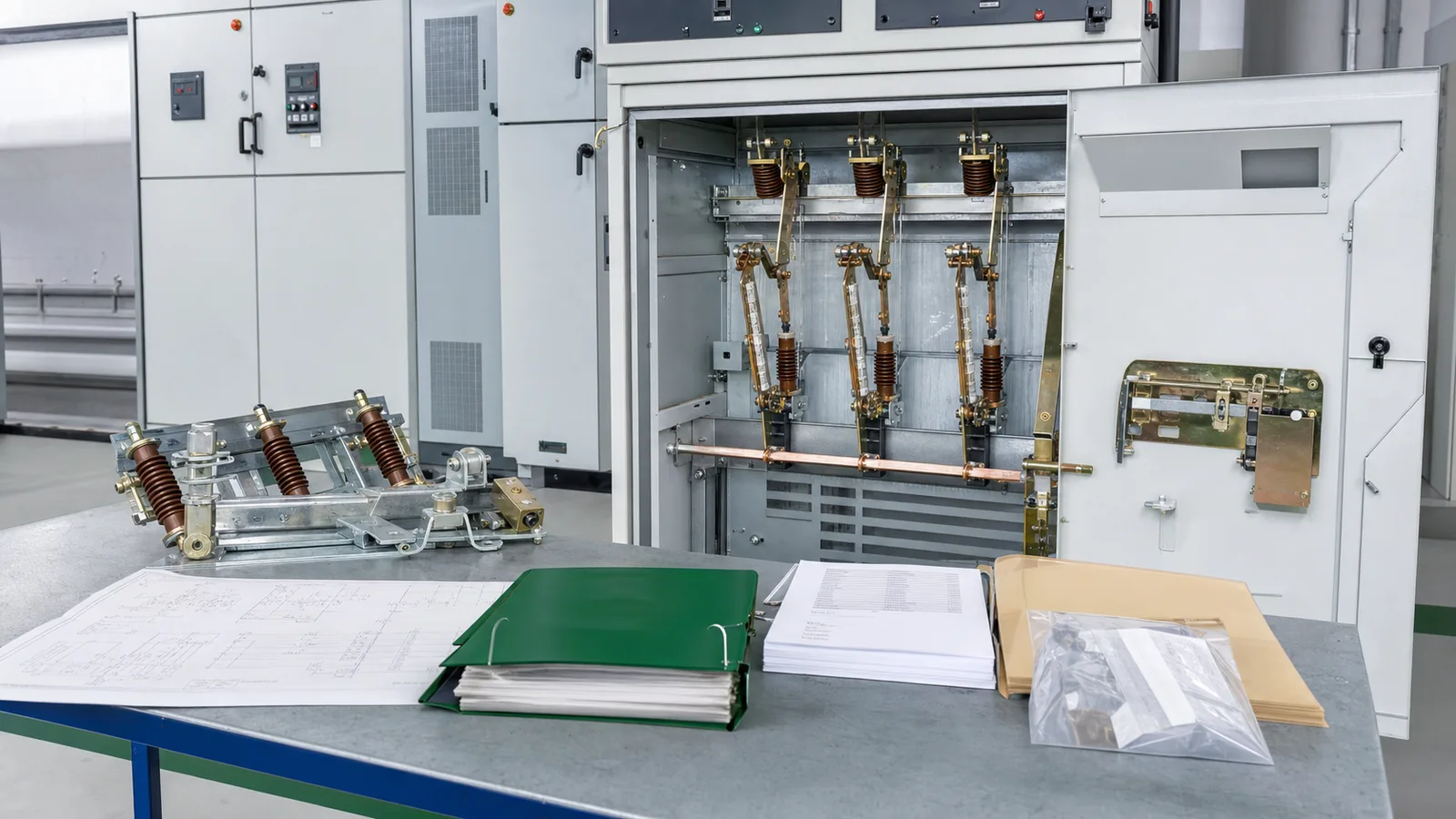
Earthing switch selection requires more than matching voltage class and short-time current. The buyer must define the grounding point, rms current and duration, peak making duty, prohibited states, operating authority, indication, auxiliary contacts, shaft side, mounting interfaces, and evidence required for the offered configuration. This guide turns those inputs into a technical-release package. It does not replace an approved switching procedure, lockout/tagout rules, absence-of-voltage verification, or site-specific interlock logic validation.
Start with the exact point that the earthing switch will ground. Identify the feeder, bus section, cable side, transformer side, or other node; define the intended maintenance zone; and list every possible source of energization. The short-circuit study and equipment evidence must apply at that point, not merely somewhere on the same voltage system.
The distribution switching equipment guide explains the separate functions of isolation, switching, protection, and earthing. For this selection, keep the earthing function distinct. The device provides a deliberate path to earth in an approved state, but its presence does not prove that the circuit is isolated or safe to approach.
Use one controlled matrix rather than scattered notes:
| Input | Project basis | Supplier response | Evidence and release condition |
|---|---|---|---|
| Grounding point | Single-line diagram and maintenance zone | Offered application point | Configuration and drawing match |
| Rated voltage and insulation | System specification | Offered ratings | Applicable data and evidence |
| Short-time duty | rms current plus stated duration | Ith and duration | Both fields explicitly confirmed |
| Making duty | Peak current at closing | Ima or equivalent declared value | Evidence applies to offered variant |
| Operating method | Manual or powered, local or remote | Mechanism and command interface | Mechanism drawing and schedule |
| State boundary | Prohibited conditions and authority | Mechanical, key, or electrical interfaces | Interlock response completed |
| Indication and contacts | Required signals and allocation | Available outputs | Position/contact schedule agreed |
| Physical interface | Shaft side, mounting, spacing, clearances | Offered arrangement | Current-revision drawing approved |
Treat a blank duration, generic family catalogue, unexplained shaft change, or unallocated contact as an open item. A matching model name is not a release decision. The live earthing switch product category is useful for model and dimensional review, but the project matrix must still reconcile the exact offered configuration against the project inputs.
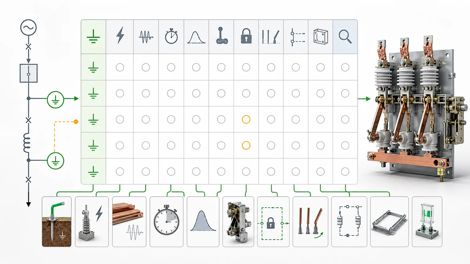
The short-circuit study should produce three separate selection fields at the grounding node:
Do not merge them into a single fault level. Short-time withstand current, often identified as Ith, is an rms value carried by the closed earthing switch for a stated time. Making capacity, often identified as Ima, is the peak current associated with closing onto an energized circuit under the applicable rated condition. A supplier response that states 31.5 kA without saying whether it is rms or peak, and without stating duration, is incomplete.
Check evidence in this order: exact model and variant, rated voltage, mechanism or configuration, short-time current, duration, peak making value, test or design evidence identity, and any stated applicability limitations. A result for another phase spacing, mechanism, current class, or construction cannot be assumed to cover the offer.
The official public page for IEC 62271-102:2018 describes the scope for alternating-current disconnectors and earthing switches above 1,000 V and identifies changes concerning earthing-switch short-circuit making classification, interlocking-device requirements, position indication, operating force, and mechanical interlock testing. Use the purchased standard and project specification for clause-level requirements; the public page is only a scope reference.
Also record service conditions that can change the selection basis, including indoor or outdoor installation, altitude, ambient range, pollution or corrosion exposure, condensation risk, operating frequency, and any enclosure constraints. The broader disconnect switch category provides product-family context, but final duty acceptance belongs in the project review.

Define what the selected equipment and its interfaces must prevent, while leaving the complete system logic to the responsible project authority. Two prohibited conditions normally need an explicit project response:
These statements are selection boundaries, not an operating sequence for field personnel. The project must identify the associated upstream and downstream devices, command authority, local/remote modes, required permissives, mechanical or key interlocks, electrical interfaces, and expected behavior after control-supply or signal loss. The panel engineer and system protection or control engineer must validate the complete logic.
Keep each status source distinct. Primary blade position, mechanism end position, auxiliary contact state, remote indication, upstream-device status, and voltage indication communicate different facts. No one signal, and no equipment label, constitutes proof that the circuit is de-energized and safe to earth. Authorized personnel must make that determination under the approved site procedure.
An interface schedule should name the related device, prohibited state, interlock type, command owner, input or output, contact logic, control voltage, fail-safe expectation where specified, evidence reference, and responsible reviewer. For mechanism-level travel, position, and control interfaces, use the disconnect switch operating mechanism guide as supporting context without transferring full system-logic ownership to the equipment supplier.
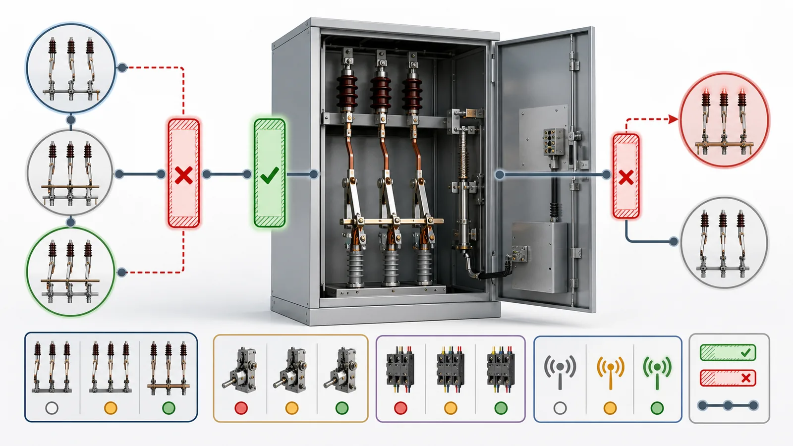
Electrical duty can match while the physical arrangement still fails. Review the mechanism and installation drawings against the current cabinet or structure drawing. Confirm:
Do not treat position indication, mechanism travel, and auxiliary contacts as one output. The project may need direct visual indication at the primary element, mechanism end-position confirmation, and separate contacts for control, interlock, remote indication, and monitoring. State which contacts are normally open or normally closed in each defined position and reserve spares only after required functions have been allocated.
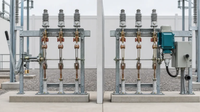
Drawing control matters. Require a model designation, drawing number, revision, orientation, dimensions, and interface notes that identify the offered variant. If a catalogue shows both left- and right-side mechanisms, the offer must say which one is supplied. If the cabinet drawing changes, reopen affected rows rather than relying on an earlier review.
The RFQ should give the supplier enough controlled information to return a configuration-level response. Include the single-line diagram reference, grounding point, rated voltage and insulation level, short-time current and duration, peak making input, frequency, service conditions, operating method, operating side, state and interlock boundary, indication and contact schedule, cabinet drawing, quantity, and required document list.
Use an RFQ checklist with three columns: required input, responsible source, and returned evidence. The project specification should control ratings and contractual requirements; the short-circuit study should control duty at the stated node; the approved single-line and cabinet drawings should control location and interfaces; and manufacturer data should describe the exact offered configuration. Where two sources conflict, flag the row instead of silently choosing one. The returned data pack should carry document numbers, revisions, model references, and an applicability statement so the reviewer can trace each answer.
Create a release evidence index beside the matrix. For each duty or interface claim, record the source document, revision, covered model, applicable characteristic, reviewer, disposition, and destination in the approved package. This index does not turn document review into independent proof of performance. It makes the basis of the technical release visible and exposes when a brochure, drawing, or test reference does not actually cover the offered arrangement.
Ask the supplier to return the exact model and variant, completed technical schedule, mechanism and mounting drawing, interlock-interface response, position/contact schedule, duty evidence, applicability statement, routine and functional test plan, and deviation list. Evidence depth should match the risk and specification; the matrix should not imply that every project requires the same document type.
Use four release states: accepted, accepted with a documented condition, revise and resubmit, or hold. Technical release remains on hold when a required field is blank, evidence cannot be traced to the configuration, the offered interface conflicts with the approved drawing, the interlock response is incomplete, or a deviation lacks an authorized disposition.
Before placing the order, confirm that every input has an owner and disposition, applicable documents are revision-controlled, accepted differences enter the technical schedule, and open conditions have explicit closure rules. For project-specific selection support, send the controlled input package through the XIYA POWER contact page; the buyer and responsible project engineers retain approval authority.
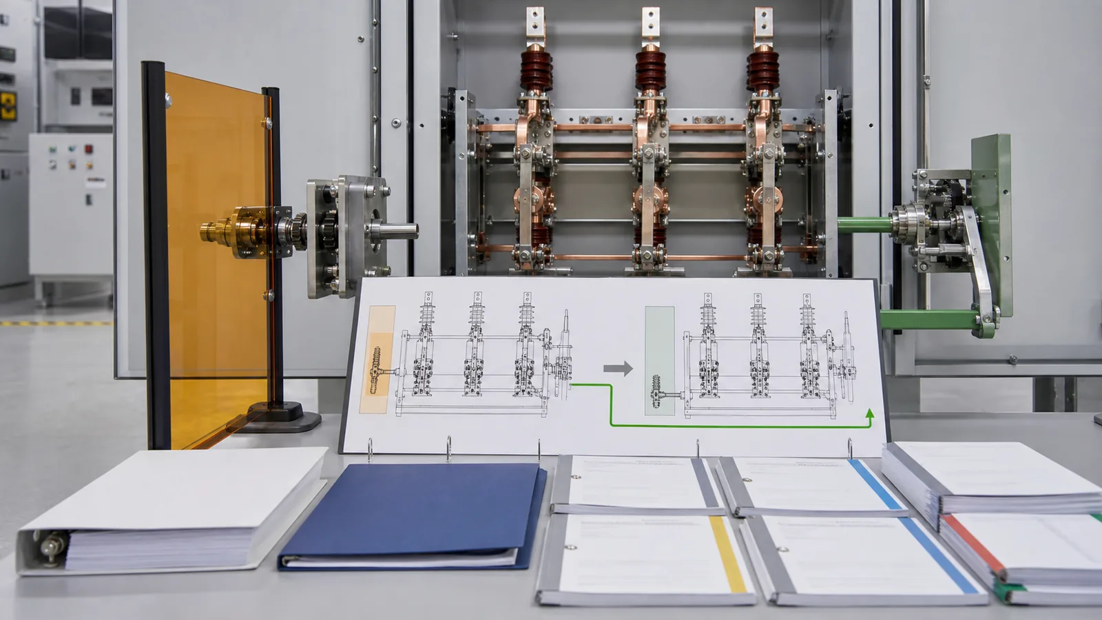
Representative engineering review only. This is not a XIYA POWER customer, utility, factory, field, test, commissioning, maintenance, outage, or service case. All values are illustrative and non-universal.
Consider a 12 kV indoor metal-clad feeder panel. The project study gives 31.5 kA rms for 3 s at the earthing point and an 80 kA peak making input. The project requires local manual operation, local position indication, and two allocated auxiliary contacts. Its state boundary prohibits closing outside the approved isolated state and prohibits energization while the earthing switch is closed. The cabinet drawing requires a right-side operating shaft.
The first offer states 31.5 kA but leaves the duration blank. It provides no configuration-applicable evidence for the 80 kA making input, and its mechanism drawing shows a left-side shaft. The returned package also lacks the completed interlock-interface response and the position/contact allocation.
The review should not infer compliance from the current value or model family. Hold technical release until the supplier confirms the 3 s duration for the offered configuration, provides applicable making-duty evidence, revises the drawing to the required right-side shaft or records an accepted deviation, and completes the interlock and contact schedules. This is a documented selection decision, not a claim that equipment was installed or that any operational outcome occurred.
Define the grounding point, maintenance zone, possible energization sources, system voltage, insulation level, rms short-time current, duration, peak making input, service conditions, mechanism, operating side, prohibited states, command authority, indication, contact allocation, cabinet interfaces, evidence, and approval responsibilities.
It is the rated peak current associated with the earthing switch closing under the applicable short-circuit making condition. The project input comes from the study at the grounding node and must be matched to evidence for the offered model and configuration.
No. Short-time withstand is an rms current carried for a stated duration. Making capacity is a peak current associated with closing. Both values and the required duration must be separately stated and reviewed.
Specify the prohibited states, related devices, command authority, local/remote boundary, required mechanical, key, or electrical interfaces, signal-loss behavior where applicable, and evidence. The responsible project authority must validate the complete interlock logic.
No. Blade position, mechanism indication, auxiliary contacts, remote signals, and voltage indication are individual status inputs. None replaces approved isolation, absence-of-voltage verification, lockout/tagout, permit-to-work, or other site safety procedures performed by authorized personnel.
Approve the current single-line and cabinet drawings, the offered mechanism and mounting drawing, applicable short-time and making-duty evidence, the interlock-interface response, position/contact schedule, technical schedule, and deviation record. Hold release until conflicts and open conditions are formally resolved.