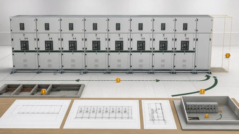
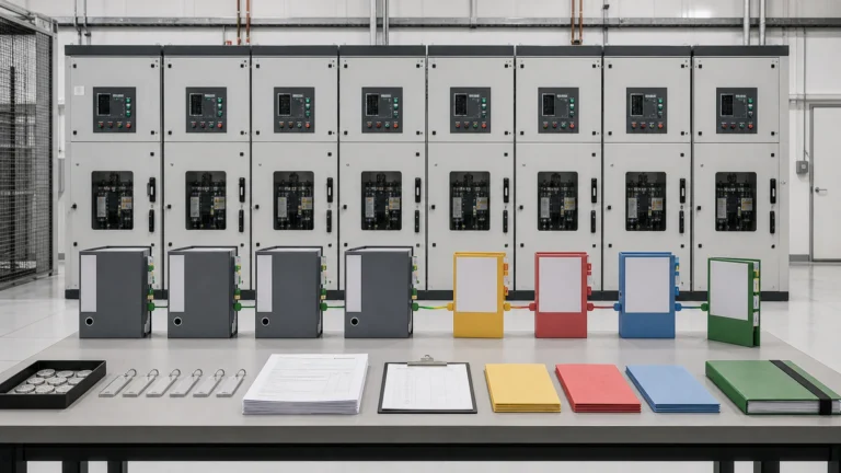
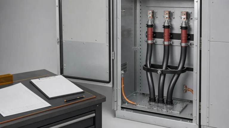
Quotation form
Send an inquiry
Start with the basics. Our team can follow up for missing drawings, standards or packing details.
Submitted details are used only for quotation, technical review and project communication.

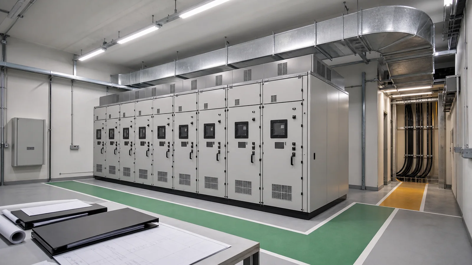
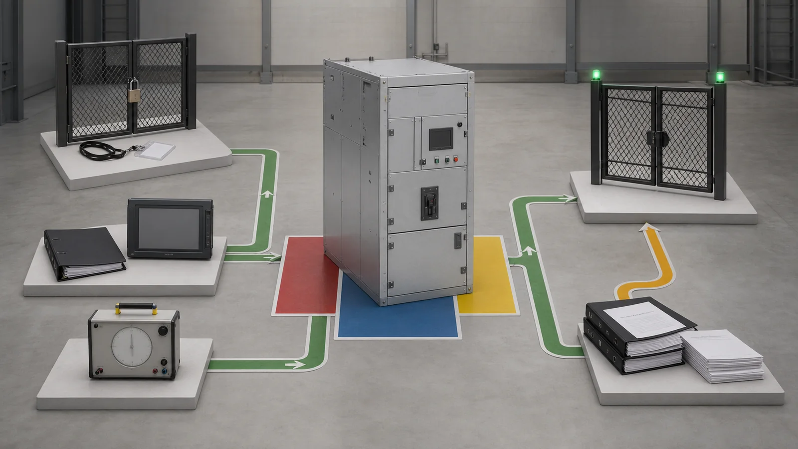
Switchgear internal arc classification AFL AFLR is common RFQ shorthand, but selection requires a complete declaration, not a catalogue label. Define who can access the installation, which enclosure sides remain accessible, the project arc current and duration, the exact lineup/compartment configuration, and the room pressure-relief conditions. Then require evidence that maps those conditions to the offered assembly.
Visual disclosure: all images are generated illustrative technical visualizations, not XIYA POWER factory, design, test, FAT, manufacturing, installation, commissioning, or field photographs.
Internal arc classification (IAC) under IEC 62271-200 describes a metal-enclosed switchgear assembly tested under defined internal-arc conditions. The declaration combines the accessibility type, classified sides, prospective arc current, and arc duration. All elements are needed for comparison.
A complete example is IAC AFL 20 kA, 0.5 s. Schneider Electric’s official IAC accessibility FAQ explains the public notation. Type A restricts access to authorized personnel; F/L designate the front/lateral classified sides; 20 kA is the stated current; and 0.5 seconds is the stated duration. The same source defines types B/C and the R rear-side designator. Clause-level requirements remain controlled by the purchased standard, project specification, and configuration-applicable manufacturer evidence.
| Declaration element | Example | Selection meaning | Hold condition |
|---|---|---|---|
| Classification prefix | IAC | Internal arc classification is declared | Prefix missing or replaced by marketing wording |
| Accessibility type | A | Access restricted to authorized personnel | Project access model not matched |
| Classified sides | FL | Front and lateral sides are included | An accessible side is omitted |
| Arc current | 20 kA | Stated prospective arc current for the test | Project fault basis or evidence missing |
| Arc duration | 0.5 s | Stated duration for the test | Protection clearing basis unresolved |
`
`
A bare AFL or AFLR is incomplete without current, duration, and applicable evidence. The Complete Switchgear Cabinets owner provides family context, but no family name proves an IAC declaration for every bay, compartment, or installation arrangement.
Accessibility type describes who may be near the enclosure under the defined installation and operating model:
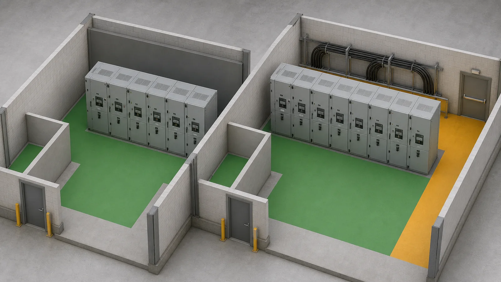
For types A and B, F is front, L is lateral, and R is rear. The manufacturer identifies the front of the equipment. The project identifies which faces people can occupy or reach during energized service, switching, inspection, or work on an isolated compartment while adjacent equipment remains energized.
| Project access condition | Required input | Decision | Supplier return | Hold condition |
|---|---|---|---|---|
| Front operating aisle only | Room plan and access rules | Confirm front-side requirement | Complete IAC code and evidence | Other sides are not demonstrably inaccessible |
| Front plus lineup-end access | End-panel and barrier arrangement | Include lateral-side review | F/L classification mapping | End condition absent from evidence |
| Rear corridor occupied while lineup/adjacent bays remain energized | Rear access and operating states | Rear side must be resolved | Applicable R evidence or accepted access redesign | AFL offered with accessible rear |
| Public presence near enclosure | Occupancy and barriers | Review type B or C need | Type/accessibility declaration | Type A is assumed without control |
The difference between AFL and AFLR is therefore not cosmetic. AFL includes front and lateral sides; AFLR also includes rear. If the rear remains accessible under an energized operating state, the project needs an applicable rear-side solution or a reviewed physical/access redesign that genuinely removes that exposure.
`
`
The fixed-versus-withdrawable decision changes compartments, access routes, and maintenance states, but does not by itself assign IAC. Use the XGN versus KYN28 project-fit guide for that upstream architecture decision, then apply the actual room and operating model here.
Derive the required arc current and duration from current project sources. Current inputs come from the short-circuit study at the switchgear location, including applicable source contributions and operating configurations. Duration inputs come from the approved protection clearing basis, including the relevant primary and backup scenario defined by the project risk model.
Utility rules and the project specification may set additional requirements. Record each value’s source, revision, system state, and owner. Do not select an IAC current/duration from a catalogue maximum or a previous project.
| Input | Required source | Supplier comparison | Release evidence |
|---|---|---|---|
| Prospective arc current | Current short-circuit study and operating configuration | Offered IAC current is not below the specified value | Report/declaration for exact configuration |
| Arc duration | Protection clearing basis and project rule | Offered duration is not below the specified value | Applicable test duration and protection reference |
| Accessibility/side requirement | Room, barriers, occupancy, and operating states | Offered code covers every required side/type | Side mapping and installation evidence |
| Variant/configuration | Bay schedule, compartments, end panels, relief system | Offered assembly remains within evidence scope | Applicability matrix and deviations |
A numerically higher current or longer duration is not sufficient by itself. It cannot repair a missing classified side, wrong accessibility type, different pressure-relief arrangement, or inapplicable report. The MV switchgear RFQ data guide owns the wider SLD, bay, fault-duty, room, and protection input package.
Internal-arc evidence is obtained with defined equipment and installation conditions. The project must show that the offered lineup and room replicate those conditions or remain within a documented applicability boundary.
| Installation input | Project return | Evidence question | Hold condition |
|---|---|---|---|
| Wall or free-standing arrangement | Dimensioned room/GA | Was the same arrangement represented? | Arrangement differs without review |
| End panels and lineup length | Bay schedule and end treatment | Are ends and representative cubicles covered? | End/lineup scope unclear |
| Compartments and bay variants | Configuration schedule | Which internal-arc test locations apply? | Variant inferred from family name |
| Doors, covers, and relief flaps | Operating-state schedule | Does the tested state match normal service? | Required part/state omitted |
| Plenum or pressure-relief duct | Duct drawing and exhaust destination | Does the evidence include this route? | Duct/vent path not mapped |
| Ceiling, wall, and side clearances | Coordinated room drawing | Are clearances within evidence conditions? | Geometry is outside the record |
| Cable trenches and floor openings | Civil/interface drawing | Was opening treatment represented? | Uncontrolled exhaust path remains |
| Occupied areas | Access and barrier plan | Are hot gases routed away from people? | Exhaust reaches an occupied path |
`
`
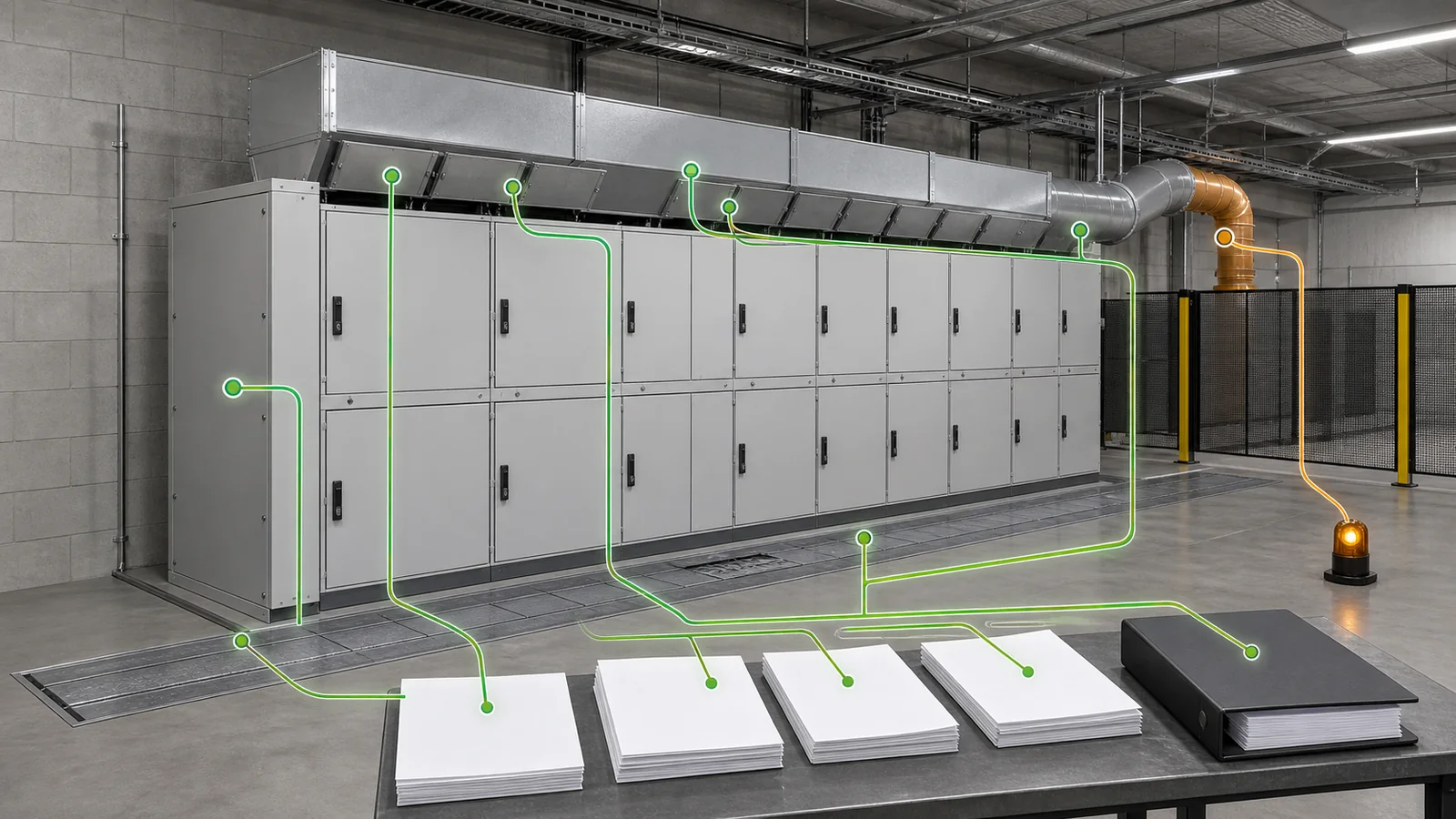
Manufacturer data should identify the tested object, lineup arrangement, compartments, relief system, room conditions, and exclusions. A different end panel, open trench, ceiling height, duct, or exhaust destination can change applicability even when the cabinet type code is unchanged.
For one common family, the KYN28 switchgear specification assigns classification, compartment, interlock, and room-interface inputs to the exact panel schedule. CAB-07 does not infer IAC from the KYN28 name; it requires the offered configuration’s evidence.
Issue an IAC RFQ checklist and data pack that normalizes every supplier return:
Normalize each return against the same project rows. Mark an entry as a project requirement, supplier declaration, report result, applicability statement, deviation, or unresolved assumption. Record the source revision and affected bays beside it. This prevents a compliant headline on one representative cubicle from being reused silently for a different end panel, compartment, duct, or lineup arrangement.
An IAC report is not an insulation test record. The insulation resistance versus power-frequency withstand guide explains those two tests and their different outputs. Neither proves IAC, and IAC does not replace either where required.
IAC also does not prove that an internal arc cannot occur, that no injury is possible, or that equipment remains serviceable afterward. It does not establish LSC, partition class, IP rating, general fault duty, insulation level, interlock performance, earthing, pressure-relief adequacy for a different room, or every variant in a product family. Avoid arc-proof; use internally arc classified for the stated type, sides, current, duration, configuration, and installation conditions.
The complete FAT evidence pack, routine reports, deviations, retests, and final release records are a separate downstream activity. CAB-07 defines the IAC selection evidence that must enter that later pack.
Representative engineering review, not a XIYA POWER customer, factory, design, test, FAT, installation, commissioning, or field case. All values and room conditions are illustrative and non-universal.
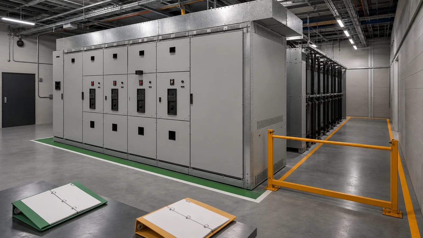
A 12 kV lineup has a project input of 20 kA and a protection clearing basis of 0.7 s. The supplier headline is IAC AFL 25 kA, 1 s. The room has a 1,500 mm front operating aisle, 800 mm lateral access at the lineup end, and an 800 mm rear cable corridor. Authorized personnel may use the rear corridor while adjacent bays remain energized.
| Required input | Decision | Supplier return | Release evidence | Hold condition |
|---|---|---|---|---|
| Type A access | Authorized-only operating area | A stated | Applicable report required | None at notation level |
| Project current/duration | 20 kA and 0.7 s basis | 25 kA and 1 s stated | Exact configuration not yet mapped | Numeric headline alone is insufficient |
| Accessible sides | Front, lateral, and rear | AFL; rear omitted | No rear-side mapping | Accessible rear is unclassified |
| End-panel arrangement | Offered end condition must be covered | Not confirmed | Pending | Evidence applicability open |
| Pressure-relief duct | Offered duct/room path must be covered | Not mapped | Pending | Installation applicability open |
`
`
The apparently higher current and duration do not close the rear-side or evidence gaps. Decision: hold. Request an applicable AFLR offer that maps the rear side, end panel, compartments, and relief duct. Alternatively, complete a reviewed room/access redesign that genuinely removes rear accessibility during energized service. No final selection, design approval, test, FAT, installation, or release outcome is claimed.
It declares internal arc classification with accessibility type A and classified front/lateral sides. A complete declaration also states arc current and duration and requires evidence for the offered configuration.
AFL covers front and lateral sides. AFLR also covers the rear. The project decides whether rear classification is required by reviewing actual room access, barriers, and energized operating states.
No. Current and duration must meet the specified basis, but accessibility type, classified sides, configuration, room/relief conditions, and evidence applicability must also close.
No. IAC is a classification under stated test conditions. It does not guarantee that an arc cannot occur, zero injury, access to unclassified sides, or post-event serviceability.
The room defines accessible sides and the exhaust path. End panels, clearances, ducts, flaps, trenches, barriers, and occupied areas must remain within the evidence conditions for the offered lineup.
Require the complete code, report/declaration, tested object, covered bays/compartments, end arrangement, relief route, installation conditions, applicability matrix, deviations, and release-evidence path.