Quotation form
Send an inquiry
Start with the basics. Our team can follow up for missing drawings, standards or packing details.
Submitted details are used only for quotation, technical review and project communication.

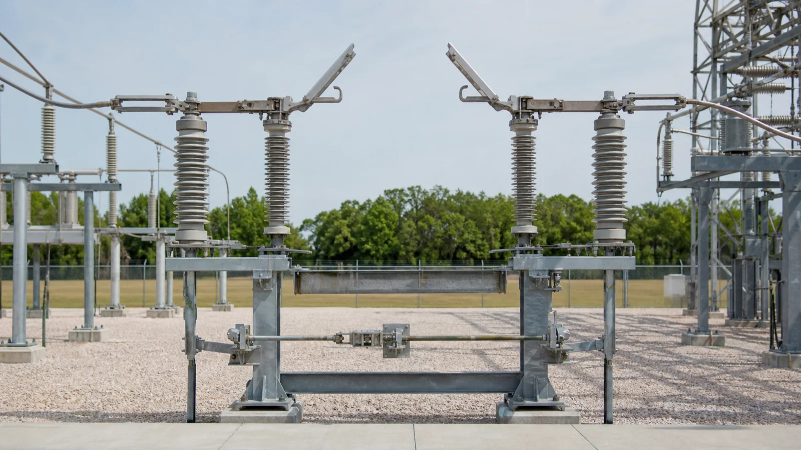
A usable outdoor disconnect switch RFQ must define the switching duty, electrical ratings, service conditions, physical interfaces, operating requirements, evidence package, and delivery boundary. Voltage and current alone are not enough. A disconnector is not automatically a load-break device, so any bus-transfer, charging, magnetizing, or induced-current duty must be stated and matched to verified capability. The goal is a technically comparable quotation for the correct outdoor disconnect switch package, not a price built on hidden assumptions.
Treat each RFQ block as a release condition. This selection matrix separates a budgetary inquiry from a data pack that can pass technical review.
| RFQ block | Required input | Release question | Release evidence |
|---|---|---|---|
| Application and duty | Isolation point, operating sequence, current-switching duty if any | Is every making or breaking duty declared? | One-line diagram and duty statement |
| System and ratings | System voltage, highest voltage for equipment, insulation levels, normal current, short-time and peak withstand | Do the values come from approved system studies? | Rating schedule and short-circuit study |
| Environment | Altitude, temperature, pollution, corrosion, wind, ice, seismic requirement | Are exceptional service conditions identified? | Site data sheet and project specification |
| Layout and terminals | Break configuration, phase centers, open envelope, support and terminal interfaces | Can the offered assembly fit the structure and conductor arrangement? | GA, structure drawing, and terminal schedule |
| Operation and control | Manual or motor operation, pole arrangement, control supply, indication, auxiliary contacts, interlocks | Can the mechanism interface with the operating philosophy? | Control or I/O schedule and interlock narrative |
| Tests and documents | Standards hierarchy, evidence acceptance, routine tests, inspection points, drawing register | Is the approval package defined before quotation? | Document register and inspection requirements |
| Commercial and logistics | Quantity, destination, milestones, packing, spares, deviations | Can offers be compared on the same supply boundary? | Commercial schedule and deviation list |
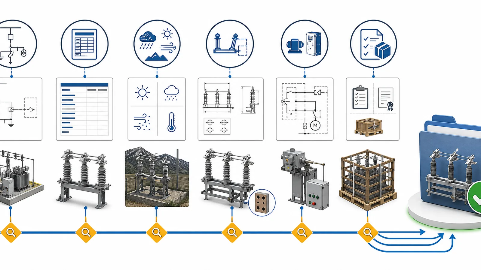
A budgetary response may be possible with a voltage class, current rating, quantity, and general arrangement. A firm technical offer needs the full release evidence. Blank fields should be marked as open clarification items rather than filled with vendor assumptions. That keeps the technical release controlled and makes exceptions visible during bid comparison.
The first decision is functional. A disconnector normally provides a visible isolation gap after another device has cleared the circuit. It should not be treated as a load-break switch unless the required current duty is declared and the offered design has applicable evidence. The existing disconnect switch and load-break switch comparison explains that basic boundary; the RFQ must convert it into project data.
| Duty or condition | Buyer input | Why it changes the offer | Acceptance source |
|---|---|---|---|
| Isolation after a breaker opens | Operating sequence and isolation points | Establishes the normal no-load switching boundary | Approved SLD and switching narrative |
| Bus-transfer current | Magnitude and circuit arrangement | May require a specifically verified transfer-current capability | Switching study and manufacturer data |
| Line or cable charging | Line/cable data and calculated duty | Arc-control requirements depend on the stated duty | Project calculation and type-test relevance review |
| Transformer magnetizing current | Transformer data and intended sequence | The current and transient duty must not be assumed | Transformer data and switching study |
| Induced current | Parallel-circuit geometry and study result | Can affect the required current-switching capability | Project study and manufacturer data |
| Earthing-switch making duty | Fault level and required earthing sequence | A fault-making earthing switch is a separate rated function | Short-circuit study and offered-device evidence |
| Interlocked sequence | Breaker, disconnector, and earthing-switch permissives | Determines mechanism and auxiliary interface requirements | Interlock narrative and control schedule |
The scope of IEC 62271-102:2018 covers AC disconnectors and earthing switches above 1,000 V for indoor and outdoor service. Its published summary also identifies current-switching duties, endurance, ice coating, interlocking, isolating distance, position indication, and temperature testing as areas that may need specification or verification.
Arcing horns, whips, or other attachments do not create unlimited load-breaking capability. If a project requires current switching, state the duty and request evidence applicable to the offered arrangement. If the duty belongs to a load-break switch or circuit breaker, use the correct equipment family within the broader distribution switching equipment architecture.
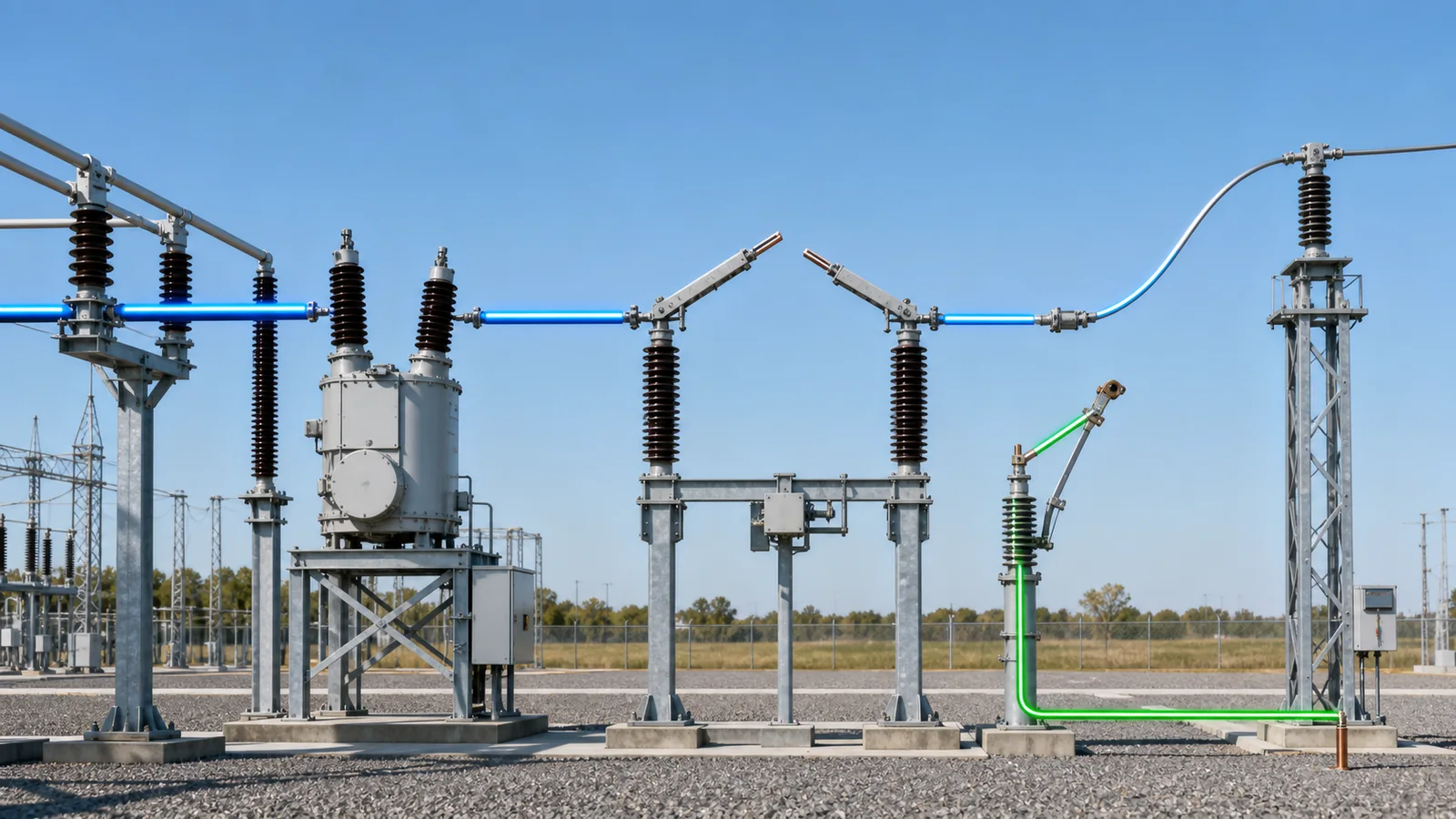
Populate the rating schedule from the one-line diagram, insulation-coordination work, short-circuit study, site data, and project specification. Do not copy a generic nameplate row into the RFQ.
| Parameter | What to state | Review boundary |
|---|---|---|
| Nominal system voltage and highest voltage for equipment | Both values and the governing standard | They are related but not interchangeable fields |
| Frequency and grounding | System frequency and grounding method | Influences insulation and switching review |
| Rated normal current | Continuous-current requirement and applicable ambient assumptions | Confirm against conductor and temperature-rise requirements |
| Short-time withstand current | RMS current and duration | Must align with protection clearing time and study results |
| Peak withstand current | Required peak value | Do not infer it without the governing project basis |
| Insulation levels | Lightning-impulse and power-frequency values, including across the open gap where required | Confirm from insulation coordination and standard hierarchy |
| Current-switching duty | Type and magnitude, or an explicit statement that none is required | Match to evidence for the offered design |
| Mechanical endurance | Required class or operating-cycle basis | Tie to operating frequency and maintenance philosophy |
| Pollution and creepage | Site severity and required creepage basis | Coordinate the insulator and complete assembly |
| Altitude and temperature | Site elevation and minimum/maximum ambient | Request the manufacturer’s correction or suitability statement where needed |
| Wind, ice, and seismic input | Governing loads or project classifications | Used for equipment and support-structure review |
| Corrosion protection | Environment and coating/material requirement | Include fasteners, linkages, terminals, and mechanism enclosure |
| Terminal loads | Static, dynamic, and torsional loads at each terminal | Coordinate rigid terminals, conductors, and flexible connectors |
Avoid entries such as “standard insulation” or “normal outdoor conditions” unless the referenced standard and service-condition limits are identified. These phrases transfer an unresolved engineering decision into the quotation. A clean RFQ either supplies the value or records who must confirm it before release.
This section of the RFQ defines interfaces, not a universal mechanism design. The buyer states the required operation and signals; the manufacturer confirms the offered mechanism, torque margin, synchronization, enclosure, and documentation.
Operating arrangement
Control and indication
Interlock schedule
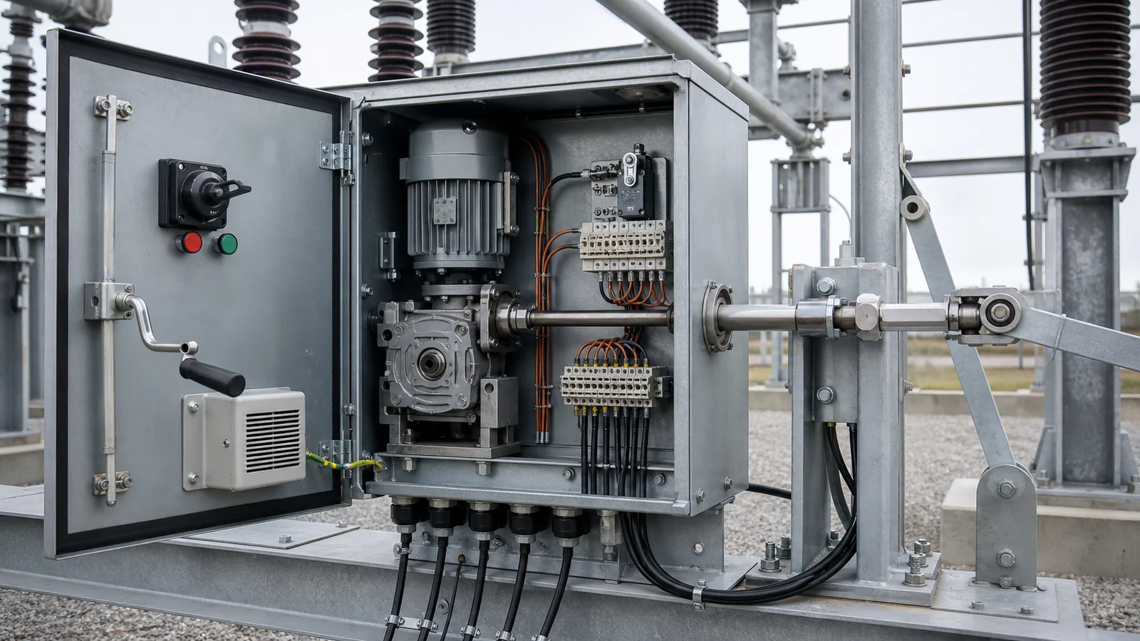
The evidence source for this block is the approved control philosophy, project specification, protection/control I/O list, and manufacturer data for the offered mechanism. If the logic is still under development, identify open interfaces in a controlled clarification register instead of allowing each bidder to invent a different control boundary.
The RFQ must show where the disconnector fits and what connects to it. Break style is a layout input, not decoration: center-break, double-break, vertical-break, or another arrangement changes phase spacing, open-blade envelope, support geometry, and drive layout.
Provide or define:
Place these inputs on the SLD, GA or envelope drawing, structure/foundation drawing, terminal schedule, and interface list. When a drawing is not ready, provide the equivalent dimensions and mark the final drawing as an approval hold point. This is enough for an RFQ review without turning the article into an installation procedure.
Use the general high-voltage equipment RFQ checklist as the project-level foundation, then add the disconnector-specific schedule below.
RFQ checklist
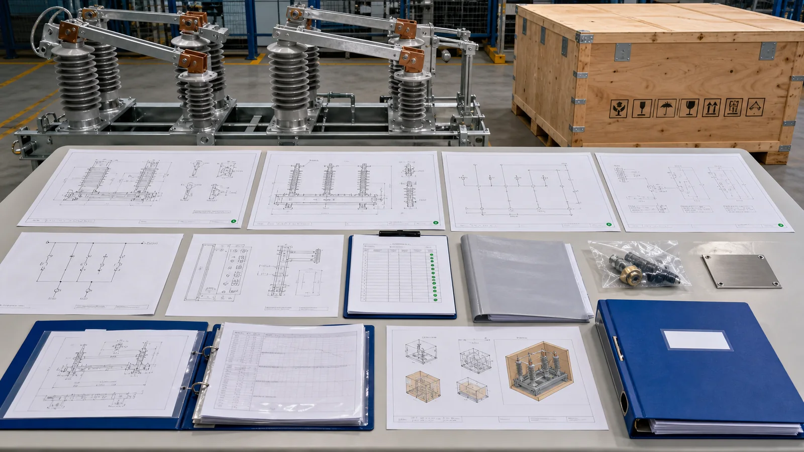
Representative engineering review – illustrative data-quality example, not a XIYA POWER customer project
An inquiry states 72.5 kV as the highest voltage for equipment, 1,250 A normal current, 31.5 kA for 3 s short-time withstand, motor-operated center-break construction, and 110 VDC control. Those values create a useful starting row, but they do not support technical release by themselves.
The missing data include system grounding, insulation levels, peak withstand current, any current-switching duty, terminal loads, site wind/ice/seismic conditions, pollution and corrosion requirements, auxiliary-contact allocation, interlock narrative, drawing interfaces, standards hierarchy, and evidence schedule. The correct response is a controlled clarification list and a technical hold. The sample does not identify a XIYA model or prove product capability; it demonstrates how apparently precise numbers can still leave the supply boundary incomplete.
Send the completed schedule, SLD, interface drawings, and document requirements through the XIYA POWER RFQ contact for model matching, deviation review, and quotation.
Provide the switching function, rated values, service conditions, physical interfaces, mechanism and control requirements, interlocks, evidence schedule, quantity, destination, packing, spares, and delivery milestones. The required input should be traceable to the SLD, studies, site data, drawings, and project specification.
No. They do not define insulation levels, fault withstand, switching duty, environment, terminal loads, control supply, interlocks, layout, or evidence. They may support a budgetary response, but not a technically comparable offer.
Not by default. A disconnector primarily provides isolation. Some designs can perform defined limited current-switching duties when specifically rated and verified. Declare the actual duty and request evidence for the offered configuration; use a load-break switch or circuit breaker when the required duty belongs to those devices.
State breaker permissives, main-blade/earthing-blade interlocks, key-transfer sequence, local/remote logic, manual-operation blocking, maintenance lockout, position discrepancy, and required alarms. Identify the signal source, destination, contact rating, and fail-safe expectation where the project defines one.
Send the current SLD, GA or envelope drawing, support/foundation interface, terminal schedule, and control or I/O schedule. If final drawings do not exist, provide dimensional constraints and mark drawing approval as a hold point.
Agree the standards hierarchy, acceptable type-test relevance, routine tests, inspection points, required factory/site checks, drawing register, calculation and record package, nameplate language, spare-parts list, and final as-built handover. This prevents evidence gaps from appearing only after manufacture.



