Quotation form
Send an inquiry
Start with the basics. Our team can follow up for missing drawings, standards or packing details.
Submitted details are used only for quotation, technical review and project communication.

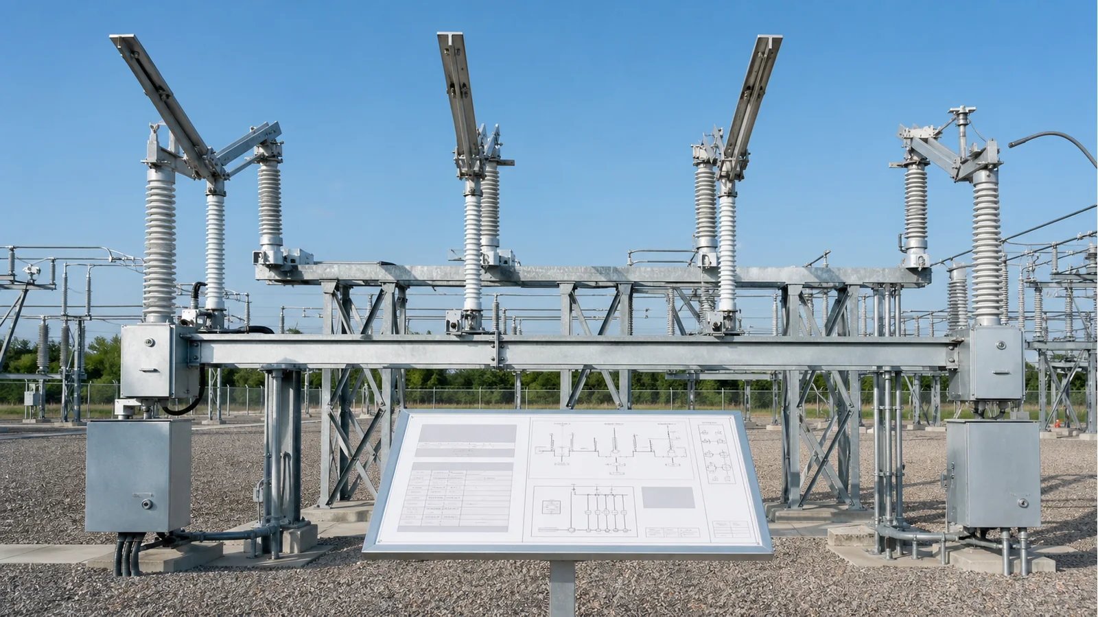
A usable 33-132 kV disconnect-switch specification starts with two different voltage fields: nominal system voltage and highest voltage for equipment. In many IEC-based projects, a nominal 132 kV network uses 145 kV equipment, but the project standard and insulation-coordination basis control the final value. The schedule must then define current and fault withstand, insulation across the open gap, any limited current-switching or earthing duty, mechanism and control interfaces, physical connections, site deviations, and evidence for the exact offered assembly. 132 kV disconnect switch, 2,000 A is a search phrase, not a releasable specification. Start with the intended outdoor disconnect switch configuration, then close every technical hold point below.
Nominal system voltage identifies the network on the single-line diagram. Highest voltage for equipment, often written as Um, identifies the equipment class and anchors the applicable insulation requirements. Copying the network voltage directly into the equipment-rating field can therefore select the wrong class.
The official page for IEC 62271-102:2018+AMD1:2022 states that the standard applies to AC disconnectors and earthing switches for indoor and outdoor installations above 1,000 V and up to 60 Hz. Its published change summary also identifies ratings, current-switching capability, ice coating, interlocking, isolating distance, position indication, temperature testing, and extension of type-test validity as controlled subjects. The project must still define whether IEC, a national adoption, a utility specification, or another agreed hierarchy governs the purchase.
This selection matrix shows common IEC procurement starting points, not universal conversions:
| Nominal network voltage | Common highest voltage for equipment | Release condition |
|---|---|---|
| 33 kV | 36 kV | Confirm from the project standard and insulation basis |
| 66 or 69 kV | 72.5 kV | Confirm the network designation and adopted class |
| 110 or 115 kV | 123 kV | Confirm utility and insulation-coordination requirements |
| 132 kV | 145 kV | Confirm before assigning insulation ratings or drawings |
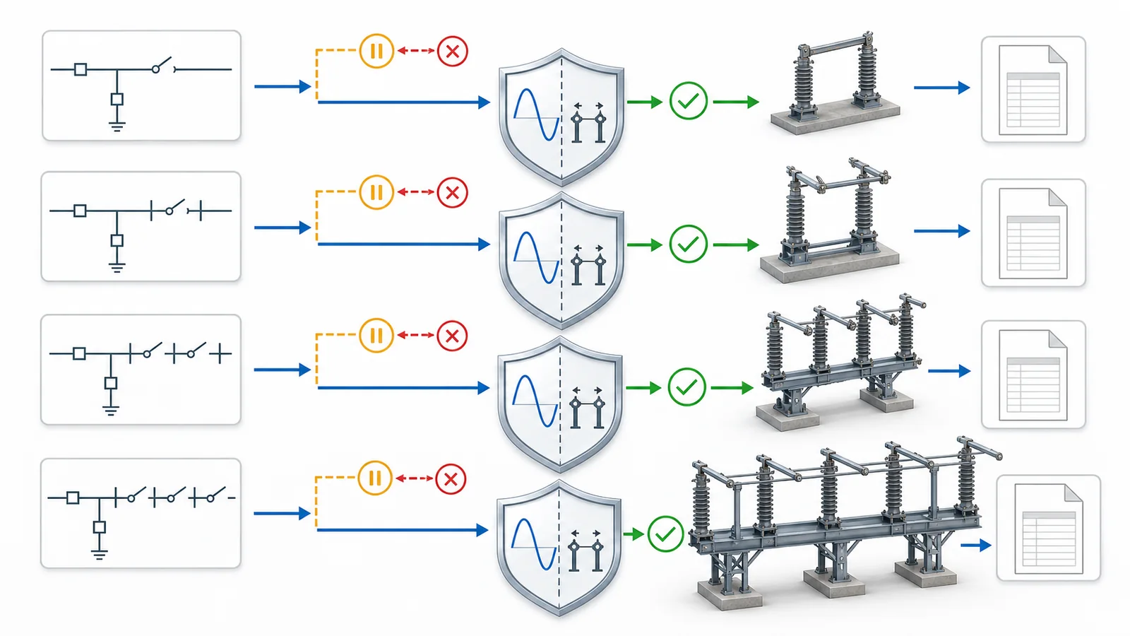
Record both voltage fields, frequency, grounding arrangement, standard edition, project deviations, and the source document for each entry. If the equipment class is open, the insulation schedule and dimensional release must remain open as well.
The standards hierarchy also needs a conflict rule. A utility specification may add requirements to a national adoption of IEC, while a project schedule may define site-specific values. The buyer should state which document governs when those sources differ and require every bidder to record exceptions against the same hierarchy. Otherwise two quotations can appear to offer the same 145 kV switch while using different insulation, service-condition, or evidence assumptions.
Rated voltage and normal current do not define a complete disconnector. Populate each field from the one-line position, load-flow and short-circuit studies, insulation coordination, switching study, and project specification.
| Required field | Engineering source | Acceptance evidence | Hold condition |
|---|---|---|---|
| Highest voltage for equipment | System and insulation basis | Declared equipment class | Nominal and equipment voltage are conflated |
| Rated normal current | Load and thermal basis | Manufacturer rating for offered assembly | Ambient or conductor basis is unresolved |
| Short-time withstand current and duration | Short-circuit and clearing-time study | Matching RMS current and duration | Fault value or duration is missing |
| Peak withstand current | Approved fault basis | Declared peak rating | Peak is inferred without the governing basis |
| Lightning-impulse withstand | Insulation coordination | Phase-to-earth and open-gap values as applicable | Levels are copied from an unrelated class |
| Power-frequency withstand | Insulation coordination | Declared duration and applicable values | Open-gap requirement is not addressed |
| Current-switching duty | Operating study and sequence | Specifically declared capability and evidence | Duty is inferred from hardware or product name |
| Integral earthing-switch duty | Grounding sequence and fault study | Making/withstand ratings and interlock evidence | Earthing function is assumed from arrangement |
The open isolating distance deserves a separate check. A visible gap helps show switch position, but appearance does not prove the required dielectric withstand across that gap. Likewise, arcing horns, quick-break linkages, or a motor operator do not establish bus-transfer, induced-current, capacitive-current, or load-breaking capability. The offered function, rating, standard, and applicable evidence must agree. The air-break and disconnect-switch duty boundary provides the related terminology and switching-function review.
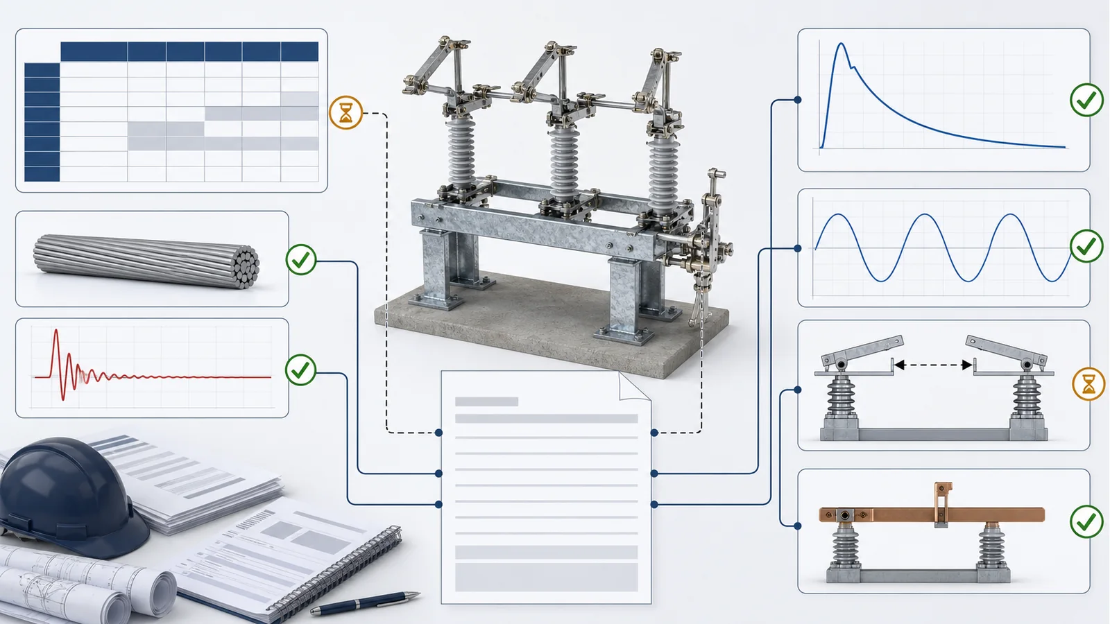
Do not import universal withstand levels, fault ratings, or current-switching classes into the RFQ. Assign project values or mark the field as a controlled clarification. A blank resolved by an unrecorded supplier assumption prevents comparable quotations.
Review the fields as one coordinated assembly. A higher insulator stack can change dimensions and terminal loading; an integral earthing switch adds a separate rated function and interlock; a transfer-current attachment can change hardware and evidence scope. The final rating schedule, GA, mechanism package, and nameplate must therefore describe the same configuration rather than four loosely related documents.
Mechanism selection changes the offered assembly, drawings, controls, and test applicability. It does not automatically change primary switching duty. Freeze the chosen break arrangement and pole-operating philosophy elsewhere in the design, then specify the interfaces for that arrangement.
| Interface | Project input | Supplier confirmation |
|---|---|---|
| Main and earthing drives | Manual or motor operation; common or separate drives | Mechanism type, mounting, travel, and operating sequence |
| Manual backup | Required location, access, lockout, and authority | Backup method and blocking provisions |
| Control supply | AC/DC source, nominal value, range, and protection | Motor, coil, heater, and auxiliary demand |
| Local/remote control | Selector states, command ownership, and fallback | Wiring logic and failure state |
| Position indication | Local indication and required remote points | Indicating device and auxiliary-contact schedule |
| Interlocks | Breaker permissive, main/earth exclusion, key logic, maintenance lockout | Mechanical/electrical implementation and drawings |
| Auxiliary contacts | Quantity, contact form, allocation, rating, and spares | Terminal numbers and guaranteed availability |
| Mechanism enclosure | Environment, ingress requirement, heater, cable entry, and grounding | Enclosure construction and interface details |
| Alarms | Supply failure, operation timeout, or position discrepancy where required | Signal logic, contact form, and terminal allocation |
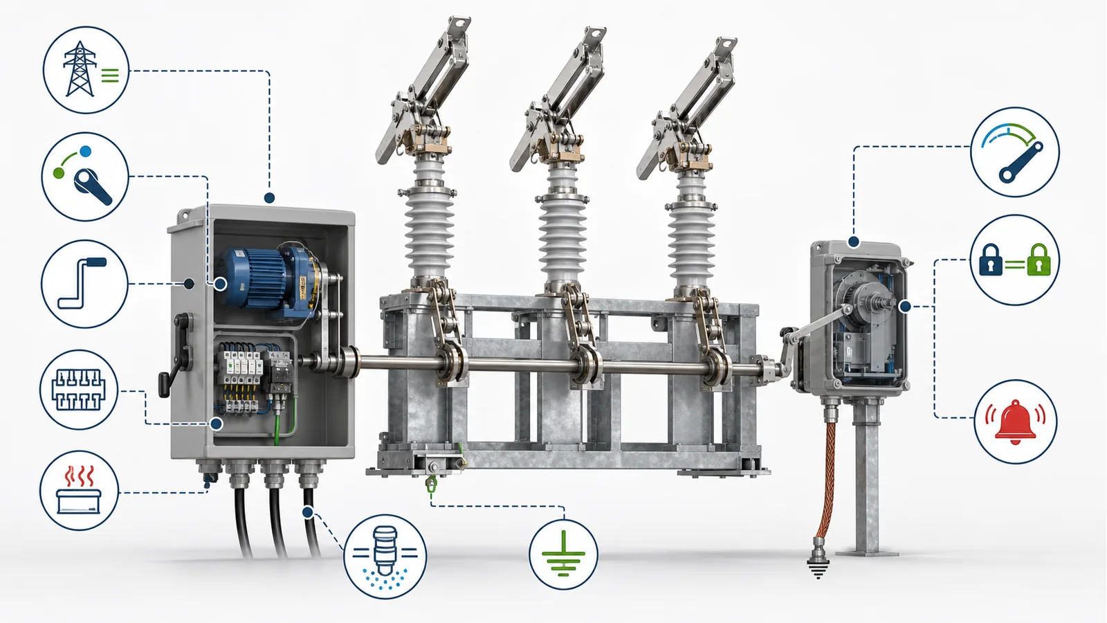
Avoid phrases such as standard motor mechanism or complete interlocks. They do not identify control voltage, command boundary, signal allocation, or responsibility. The control schematic, terminal-block schedule, interlock narrative, mechanism drawing, and operating sequence must describe one consistent assembly revision.
For three-pole equipment, also state whether a common drive operates all poles or whether each pole has its own drive, then define the required indication and discrepancy handling. This records the selected project architecture without turning the specification into a general gang-versus-independent-pole comparison. If an earthing switch is included, identify whether it has a separate mechanism and exactly which main-blade positions permit its operation.
The specification must connect the electrical schedule to project-controlled drawings. At minimum, freeze:
Site temperature, altitude, pollution, wind, ice, seismic demand, UV exposure, and corrosion category belong in the same review as declared project conditions. This article records them as specification inputs rather than prescribing universal limits. The wider distribution switching equipment structure helps route a duty to the correct equipment family, but category placement does not verify a rating or interface.
If final civil or conductor drawings are unavailable, issue controlled envelope values and make final drawing approval a hold point. A supplier GA should not silently become the source of project phase spacing, terminal loads, or safety clearances.
Technical comparison should reconcile the frozen schedule with documents for the exact offered construction. Release evidence sources include manufacturer data, the project specification, the approved short-circuit study, insulation coordination, drawings, and traceable test records. Use a compact evidence gate:
| Release record | Required match | Hold condition |
|---|---|---|
| General arrangement | Type, dimensions, interfaces, revision, and date | Drawing does not match the schedule |
| Rating/nameplate schedule | Every electrical and functional rating | Missing or differently defined field |
| Mechanism/control package | Drive, schematic, terminals, indications, and interlocks | Interface ownership is unresolved |
| Type/design evidence | Ratings and configuration of the offered assembly | Applicability is asserted but not documented |
| Routine-test plan and records | Contract tests and unit traceability | Units or acceptance criteria are unidentified |
| Material/coating records | Project-specified materials and protection system | Required evidence is absent |
| Deviation schedule | Every departure and its disposition | Verbal exception or open deviation remains |
A test report for a similar device is not automatically applicable to a changed mechanism, insulator stack, break arrangement, base frame, or arc-control component. The supplier should provide a written applicability or extension basis tied to the governing standard and offered revision. This does not mean every change requires a new type test; it means the coverage decision must be documented instead of assumed.
Use the earlier outdoor disconnect-switch RFQ checklist for the broader commercial, logistics, document-register, and submission package. DSE-05 remains the voltage-class and equipment-specification spoke.
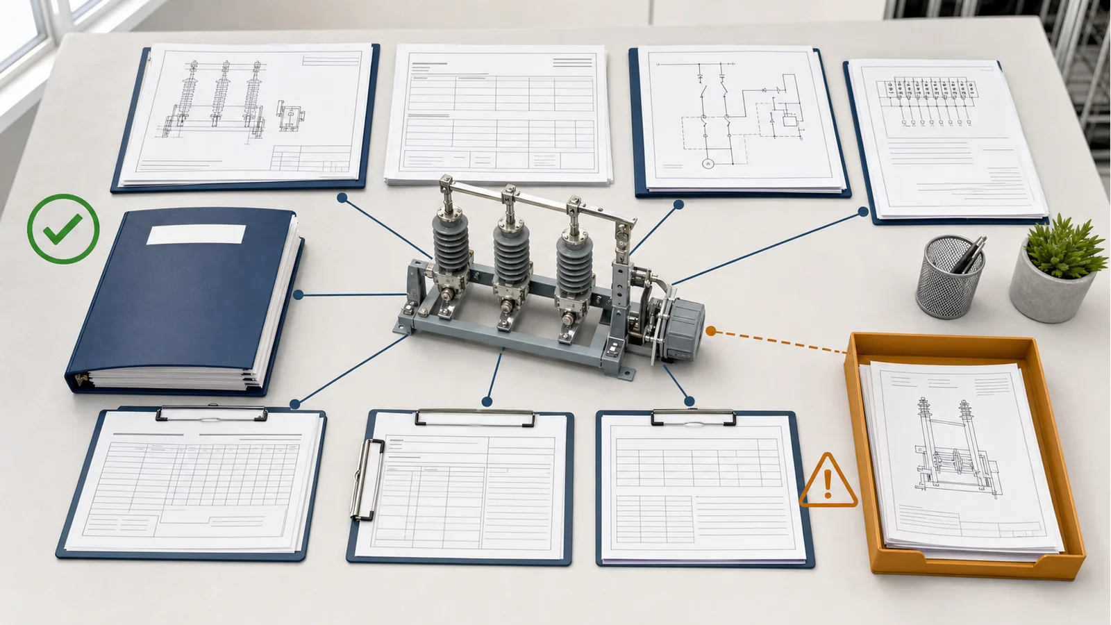
Representative engineering review, not an XIYA POWER customer project. An inquiry requests a disconnect switch for a nominal 132 kV system and states 2,000 A rated normal current. Those entries are useful, but only the 2,000 A requirement is ready for direct comparison. The voltage line still needs the project’s highest voltage for equipment; in an IEC-based schedule, 145 kV is a common starting point for confirmation.
The review holds the quotation basis until the following are resolved:
The correct output is a controlled clarification register and technical hold, not a guessed 132 kV product row. This preserves the concrete 2,000 A input without converting it into a product claim. For model matching and deviation review, send XIYA POWER the one-line, voltage and insulation schedule, fault basis, duty and operating sequence, mechanism/control requirements, site data, interface drawings, and evidence list. Review does not promise compliance before the offered assembly is verified.
In many IEC-based projects, 132 kV is the nominal network voltage and 145 kV is the highest voltage for equipment. Confirm the adopted equipment class from the project standard and insulation-coordination basis before assigning insulation levels or requesting a model.
State the required lightning-impulse and power-frequency withstand levels, including the applicable phase-to-earth and across-isolating-distance values. Their values and test basis must come from the project’s insulation coordination and governing standard.
No. Normal current addresses thermal duty. The schedule also needs equipment voltage, insulation levels, short-time current and duration, peak withstand, defined switching or earthing duties, service conditions, mechanism, interfaces, and applicable evidence.
No. It changes actuation and control interfaces. Any current-switching capability must still be specifically declared and supported for the offered assembly; it cannot be inferred from motorization.
Provide the current one-line, GA or envelope constraints, support/footprint, phase centers, terminal and conductor data, terminal loads, operating-shaft route, mechanism/control schematic, terminal schedule, interlock narrative, grounding points, and approved drawing status.
Only when a documented applicability or extension assessment shows that the report covers the change under the governing standard. Otherwise additional evidence or testing may be required. A model-family name or verbal similarity statement is not sufficient.



