Quotation form
Send an inquiry
Start with the basics. Our team can follow up for missing drawings, standards or packing details.
Submitted details are used only for quotation, technical review and project communication.

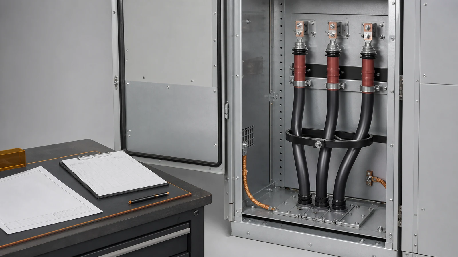
All images are generated illustrative technical visualizations, not XIYA POWER factory, cabinet, cable preparation, installation, termination, test, commissioning, maintenance, or field photographs.
A medium voltage switchgear cable entry can be released only when the exact cable set fits the same revision-controlled route, termination, CT, gland plate, and civil interface. Cabinet depth or a bottom entry note cannot prove that fit. Each feeder needs matched manufacturer data and dimensioned cabinet returns.
Start with one interface row for every incomer and outgoing feeder. Conductor size alone cannot define the cable compartment. The review also needs construction, quantity, outside diameter, bend requirements, termination technology, sensing, earthing, and entry coordinates.
The Complete Switchgear Cabinets range provides the cabinet-family context. The MV switchgear RFQ data guide owns the earlier system, lineup, protection, and preliminary cable inputs. CAB-08 begins when detailed interface drawings must close.
Use a medium-voltage cable interface selection matrix to keep each decision visible.
| Decision | Required input | Evidence source | Cabinet return | Release evidence | Hold condition |
|---|---|---|---|---|---|
| Cable basis | Feeder ID, voltage, single-core or three-core form, conductor, insulation, screen/sheath, armour | Cable schedule and manufacturer data | Declared compatible cable set | Revisions and construction agree | Cable form or source is open |
| Quantity and size | Number per phase, cross-section, outside diameter, weight | Manufacturer datasheet | Entry centers and route envelope | Every cable is represented | Outside diameter or quantity is missing |
| Bend duty | Installed and handling radii, measurement basis | Manufacturer instructions | Bend center and depicted route | Drawing uses the same basis | Radius or basis is absent |
| Termination | Kit, lug or connector, palm, hole pattern, stress-control body, straight approach | Kit drawing | Terminal and access geometry | Kit and cabinet revisions match | Envelope or interface conflicts |
| CT and earth | CT function, aperture, grouping, screen/sheath bonding route | Protection and earthing drawings | CT position and earth interface | Complete route is approved | Grouping or bonding route is open |
| Entry hardware | Gland or cleat range, opening, plate construction, sealing, bonding | Product and plate drawings | Dimensioned gland-plate schedule | Material and dimensions close | Plate or retention evidence is incomplete |
| Coordinate | Entry direction, centerline, elevation, civil revision | Approved interface drawing | Cabinet entry coordinate | Cross-reference agrees | Civil and cabinet coordinates differ |
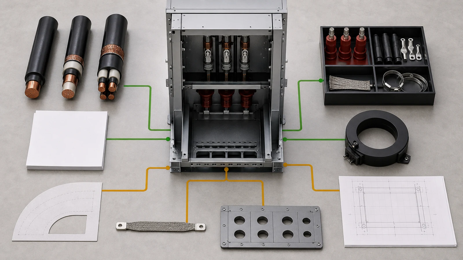
This matrix is a decision record, not a generic checklist. A required input should remain on hold when its source, revision, or owner is unresolved.
Convert top, bottom, rear, or mixed entry into a dimensioned cable-compartment section. Begin at the approved entry centerline. Show phase order, each cable centerline, bend center, terminal location, supports, adjacent devices, and access zones.
The cable manufacturer should define minimum installed and handling bend radii and explain how each radius is measured. The cabinet drawing must use that same basis. Comparing unlike centerline, inside-surface, or outside-surface dimensions produces a false result.
Cabinet depth alone does not prove fit. Terminal height, phase order, CT position, earthing switch, surge device, cleats, and internal partitions can consume the route. The innermost cable can also have a different path from the outer cables.
Treat straight approach as a separate decision. The termination-kit drawing may require a straight cable length before its stress-control body or connector. Show that envelope together with the last bend tangent, terminal palm, phase spacing, and tool access.
The route overlay should also identify removable panels and the proposed support points. A panel is not practically removable when the released cable route blocks its withdrawal. A support is not coordinated when its location conflicts with a bend or termination body.
The RMU project specification and KYN28 project specification show why cable interfaces depend on cabinet architecture. Their compartment assumptions cannot be transferred between product families without drawings.
Use this review sequence:
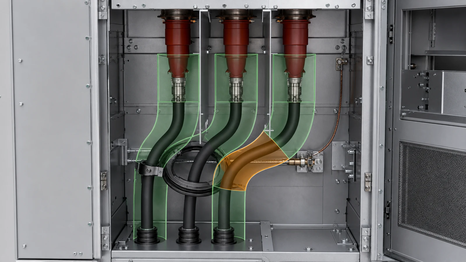
Do not replace this overlay with a universal bend multiplier or clearance. The cable, kit, and cabinet returns control the decision.
Identify the function of every CT or sensor before checking geometry. Phase CTs, core-balance or zero-sequence CTs, and other sensors do not share one routing rule.
For a through-window device, return the clear aperture, cable grouping, support arrangement, and the assumed assembly sequence. State whether the design relies on a fixed, removable, or split-core construction. An unstated sequence can make a dimensioned window impossible to assess.
Core-balance measurement also depends on which current-carrying and bonding conductors pass through the sensing window. Screen or sheath bonding can contribute to, or cancel from, the measured residual quantity depending on the approved arrangement. Therefore, the protection and earthing drawings must show the complete route.
Do not prescribe a universal screen-earth conductor path. Require the protection engineer’s approved scheme, the cable-system bonding design, and the CT manufacturer’s constraints to agree.
| CT interface | Required return | Hold condition |
|---|---|---|
| Function | Protection or metering purpose and drawing reference | CT is shown without its function |
| Passage | Clear window, grouping, cable outside diameters | Packing arrangement is absent |
| Construction | Fixed, removable, or split-core assumption | Assembly sequence is unstated |
| Earth route | Screen/sheath and armour bonding path | Residual-current boundary is unclear |
| Mechanical fit | CT body, supports, cable clearance, access | Window alone is provided |
| Secondary boundary | Terminal, wiring, and responsibility | Primary geometry and protection scope disagree |
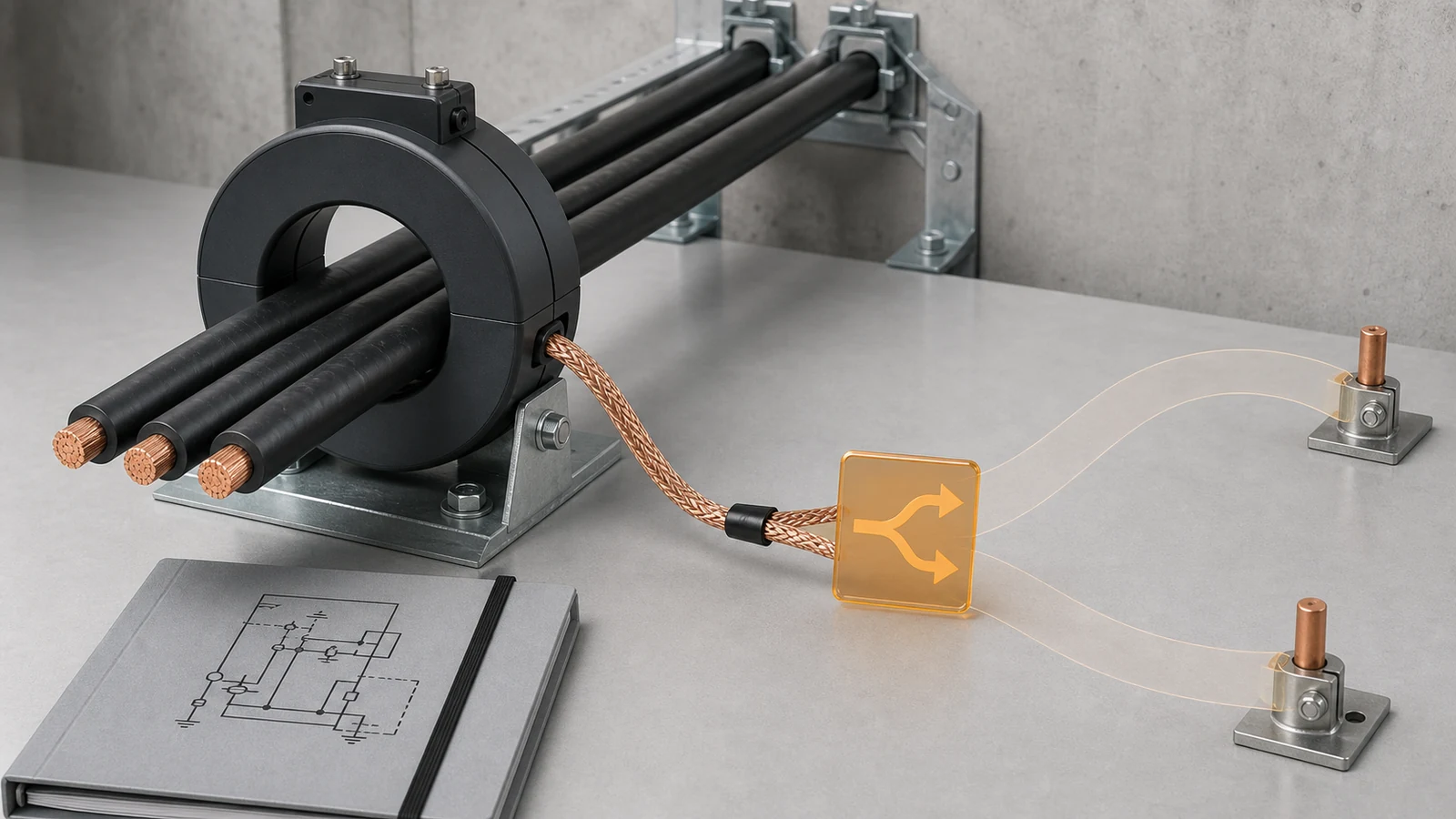
Passing the cable bundle through the aperture does not release the CT interface. Measurement intent, bonding route, support, access, and drawing revisions must also close.
Match the termination kit to the cable construction and conductor size. Then match its lug or connector, palm orientation, hole pattern, and hardware to the cabinet terminal. Show phase spacing and the complete stress-control or separable-connector envelope.
Screen, sheath, and armour bonding should cross-reference the approved cable-system earthing design. This review confirms the physical terminals and routes. It does not design the project earthing system or provide cable-preparation instructions.
Separate the gland plate from the cable restraint function. The plate provides a controlled entry and sealing boundary. Glands or cleats provide the specified retention, and may also support screen or armour interfaces when designed for that role.
For single-core AC cables, require the plate material, geometry, and magnetic or thermal basis to be declared. Do not assume an unmodified steel plate is suitable. Also avoid prescribing one universal non-magnetic material or slot arrangement without project evidence.
The plate drawing should show opening sizes and centers, segmentation, bonding, sealing, edge protection, blanking of spare entries, and removable access. Match each opening to the offered cable and gland or cleat range.
Replacement and test access remain interface requirements. Show whether a termination, connector, CT, or plate segment can be accessed without disturbing adjacent released circuits. The XGN versus KYN28 comparison owns the wider room and maintenance architecture boundary.
The final RFQ checklist should become a revision-controlled data pack. Do not release the cable interface from a folder of unrelated drawings.
| Data pack item | Required input or evidence | Technical release condition |
|---|---|---|
| Feeder cable schedule | Feeder, voltage, construction, quantity, cross-section, outside diameter | Current controlled revision |
| Cable manufacturer data | Weight, installed and handling bend radii, measurement basis | Exact offered cable identified |
| Termination-kit drawing | Kit, lug/connector, palm, body envelope, straight approach | Matched to cable and cabinet |
| Cabinet section and route overlay | Entry, bends, supports, devices, terminals, access | Dimension chain closes |
| CT and earth package | CT function, aperture, grouping, construction, bonding route | Protection and earthing drawings agree |
| Gland-plate schedule | Openings, centers, material basis, segmentation, sealing, bonding | Cable and hardware ranges match |
| Civil interface coordinate | Entry centerline and elevation from the approved handoff | Cabinet cross-reference agrees |
| Revision and deviation register | Document status, owners, open points, dispositions | No silent assumption remains |
The project specification and short-circuit study can control cable, earthing, CT, and fault-duty inputs. They cannot prove geometric fit. The route still needs manufacturer data and matched cabinet drawings.
The official IEC 62271-200 consolidated page covers prefabricated metal-enclosed AC switchgear above 1 kV through 52 kV. That public scope establishes the assembly context. It does not supply project bend radii, CT apertures, gland-plate designs, or civil coordinates.
CAB-08 may consume an approved trench or floor-opening coordinate and flag a conflict. CAB-11 owns lineup dimensions, foundations, trenches, floor openings, room access, and future extension design.
Representative engineering review, not a XIYA POWER customer, supplier, factory, cabinet design, cable preparation, installation, termination, test, commissioning, maintenance, failure, or field case. All feeder values, cable dimensions, bend requirements, drawing dimensions, termination envelopes, CT dimensions, plate details, civil coordinates, findings, and decisions are illustrative and non-universal.
The synthetic review covers one 12 kV outgoing feeder. It uses three single-core XLPE cables, one per phase. Each conductor is 1 x 630 mm2, and each finished cable has a 56 mm outside diameter. The synthetic cable datasheet states an 840 mm minimum installed bend radius.
Cabinet section drawing revision B shows 690 mm from gland-plate centerline to terminal palm. It depicts a 610 mm inner route radius without a measurement basis. The synthetic termination-kit drawing requires a 520 mm straight approach and shows a 420 mm stress-control body. The cabinet return shows 430 mm of unobstructed approach.
A 200 mm core-balance CT window surrounds all three phase cables. The screen-earth return route and assembly sequence are absent. The gland plate shows three 78 mm circular entries in galvanized steel. Magnetic or thermal evidence, hardware range, segmentation, sealing, and bonding are not returned.
The approved civil interface places the trench centerline 140 mm away from the cabinet entry centerline.
| Interface decision | Observed return | Release state | Required evidence | Hold condition |
|---|---|---|---|---|
| Routing and bend | 610 mm depicted path versus 840 mm returned minimum | Hold | Common measurement basis and revised route overlay | Radii are not reconciled |
| Termination approach | 430 mm available versus 520 mm required; 420 mm body shown | Hold | Matched kit and cabinet section with complete approach | Termination envelope does not close |
| CT and screen earth | 200 mm window; bonding route and sequence absent | Hold | Approved grouping, earth route, construction, and sequence | Protection and geometry remain incomplete |
| Gland and civil entry | Three 78 mm steel openings; 140 mm coordinate mismatch | Hold | Plate assessment, hardware range, sealing, bonding, and owner disposition | Entry and civil references disagree |
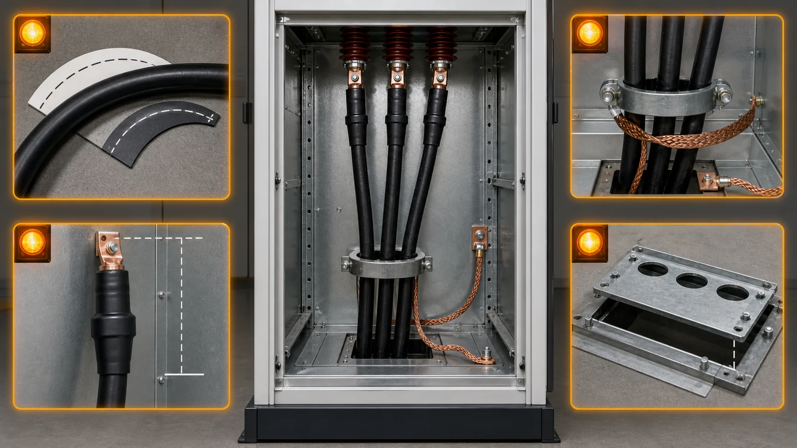
The review does not accept or reject the design. It records four independent evidence holds. No fit test, cable installation, termination, testing, commissioning, maintenance, failure, or operating result is claimed.
Provide feeder ID, voltage, cable construction, conductor, insulation, screen/sheath and armour, quantity per phase, cross-section, outside diameter, weight, bend radii, and measurement basis. Also provide the exact termination-kit and restraint hardware data.
No. The route depends on entry position, terminal height, bend center, straight approach, CTs, earthing devices, supports, partitions, and access. Verify the complete route on matched-revision section drawings.
Check CT function, clear window, cable grouping, construction assumption, support, access, assembly sequence, and the approved screen-earth route. A window dimension alone does not release the interface.
Conductive and magnetic plate geometry can affect heating around single-core AC cable entries. Require a declared material and magnetic or thermal basis for the exact opening arrangement. Do not infer suitability from a generic plate description.
Approve the cable schedule, datasheet, termination drawing, route section, CT drawing, earthing diagram, gland-plate schedule, support details, civil interface, revision register, and deviations. Cross-reference them as one package.
CAB-08 identifies and holds the conflicting entry coordinates. The cabinet and civil owners must disposition their interfaces. CAB-11 owns any lineup, floor-opening, foundation, or trench redesign.