Quotation form
Send an inquiry
Start with the basics. Our team can follow up for missing drawings, standards or packing details.
Submitted details are used only for quotation, technical review and project communication.

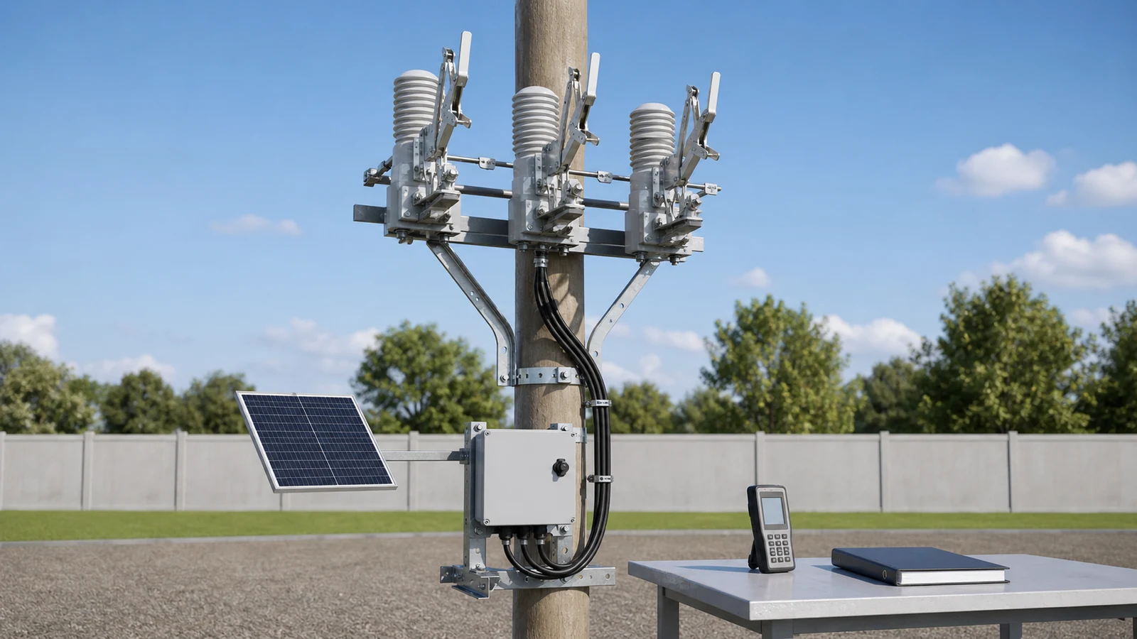
All images are generated illustrative technical visualizations, not XIYA POWER factory, installation, inspection, test, commissioning, maintenance, failure, outage, or field photographs.
Intelligent disconnector commissioning should remain on hold until the selected package, no-load duty, site layout, power, phase mapping, communication, credentials, and records agree across controlled revisions. A product label, powered terminal, or RS485 port cannot close those decisions alone.
Start after the primary device and operating package are selected. The pole-mounted intelligent disconnector product page separates the switch body, ICC terminal, handheld controller, motor cable, charging parts, and optional solar package. The Smart Grid equipment hub keeps its visible no-load isolation role distinct from fault interruption and load switching.
Use one input matrix to expose every acceptance source and hold condition.
| Decision | Required input | Acceptance source | First test or review | Release evidence | Hold condition |
|---|---|---|---|---|---|
| Site identity | Pole ID, feeder reference, phase layout, approved SLD | Project specification and site record | Match documents and photos | Signed site sheet | Identity or revision is open |
| Selected package | Manual basis, model, options, packing list | OEM manual and supplier return | Reconcile item by item | Controlled package record | Body or accessory differs |
| Duty boundary | No-load role, isolation point, authority, fallback | Approved switching plan | Review duty statement | Signed boundary record | Role or authority is unclear |
| Mounting route | Crossarm, terminal bracket, clamps, cable path | Site overlay and OEM drawing | Dimensioned comparison | Approved overlay | Route or owner is missing |
| Control power | Source, allowable range, protection, test point | OEM manual and project specification | Calibrated multimeter at approved point | Referenced measurement record | Range or point is undefined |
| Charging and storage | Charger, battery, solar data, loads, degraded state | OEM data and power schedule | Document comparison | Approved power calculation | Capacity or behavior is absent |
| Phase and status | Motor cable, phase map, feedback normal states | Wiring and point-list package | End-to-end cross-reference | Approved mapping record | Labels or states are unresolved |
| Communication | Physical layer, protocol, settings, address, points | Communication sheet and OEM data | Configuration comparison | Approved interface record | Only a port name is returned |
| Handover | Credentials, backups, deviations, test and as-left records | Commissioning plan | Completeness review | Signed release package | A required record remains open |
Use this troubleshooting chart only for de-energized, document-led triage. It is not a switching or energized test procedure.
| Symptom | First test | Likely cause | Next action |
|---|---|---|---|
| Terminal does not power | Compare the source, connector, protective device, and approved drawing | Missing supply or incompatible charging package | Hold and reconcile the power interface |
| Remote search cannot identify the device | Review device ID, serial settings, receiver, and wiring record | Address, settings, power, or connection mismatch | Obtain the controlled configuration return |
| Phase status is ambiguous | Compare motor plugs, site phase labels, and point list | Missing phase cross-reference or feedback definition | Issue an approved mapping record |
| SCADA status lacks meaning | Compare the point list, register map, quality, and normal states | Incomplete mapping or status semantics | Hold the communication release |
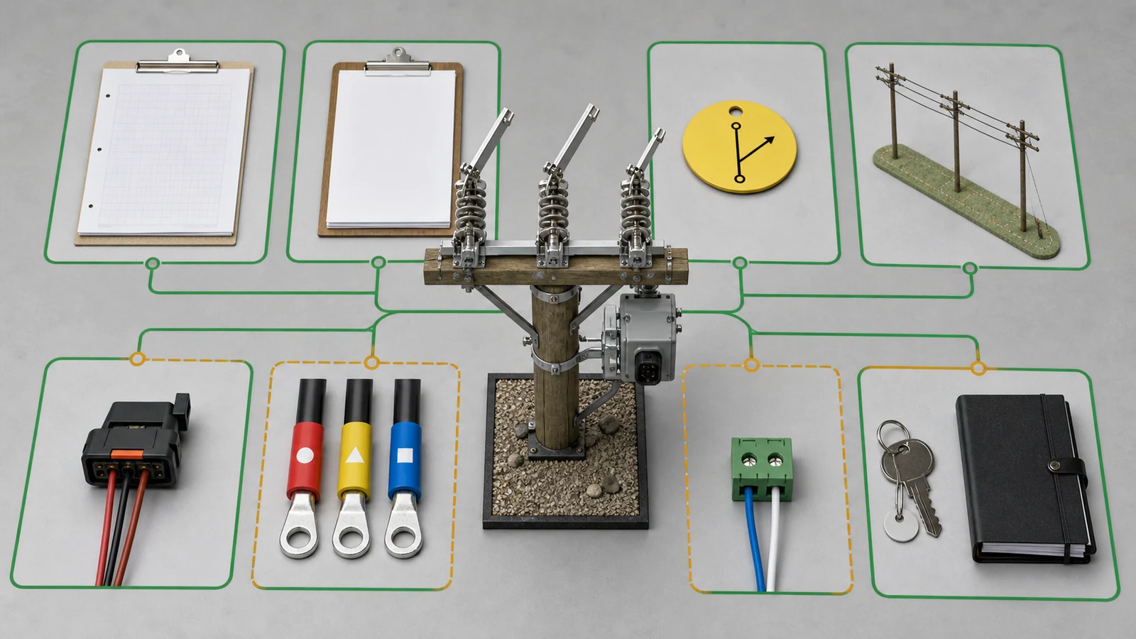
The chart records a commissioning hold. It does not prove a cause, authorize corrective work, or claim a field result.
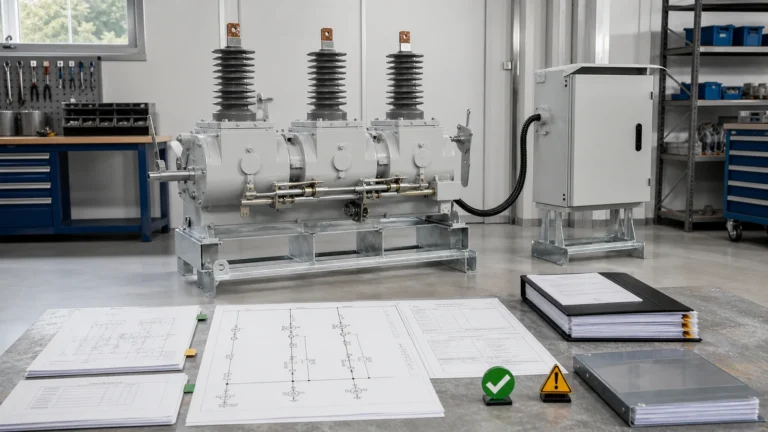
Freeze one selected manual basis before site review. DGDW1 and GWT24-24 represent separate rating and accessory layers on the product page. Do not merge their bodies, accessories, or operating details.
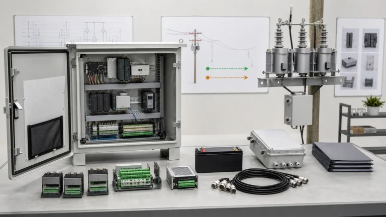
Reconcile the selected body, ICC terminal, receiver, handheld controller, motor cable, charging cable, optional solar equipment, clamps, and packing-list revision. A complete body shipment does not prove that the control package is complete.
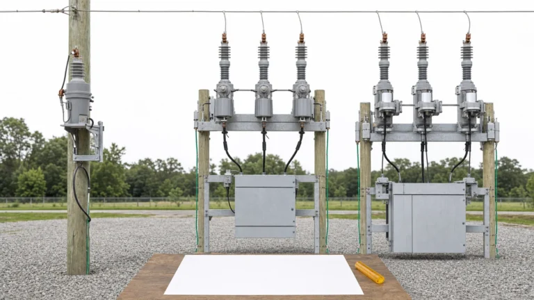
The site overlay should identify the pole, crossarm, phase arrangement, terminal position, cable route, equipment clearances, exposure, access, and responsibility for user-prepared brackets. Photographs support the overlay but do not replace dimensions or phase identification.
Confirm the visible isolation point, downstream role, no-load duty, operating authority, and local or manual fallback. The feeder automation design-input guide owns topology and system states. The feeder device-role guide owns role assignment. SG-07 consumes those approved decisions.
The public IEC 62271-102:2018 page covers AC disconnectors and earthing switches for indoor and outdoor installations above 1,000 V and through 60 Hz. That scope does not supply the selected package, site layout, control-power range, communication profile, commissioning method, acceptance limits, or project release.
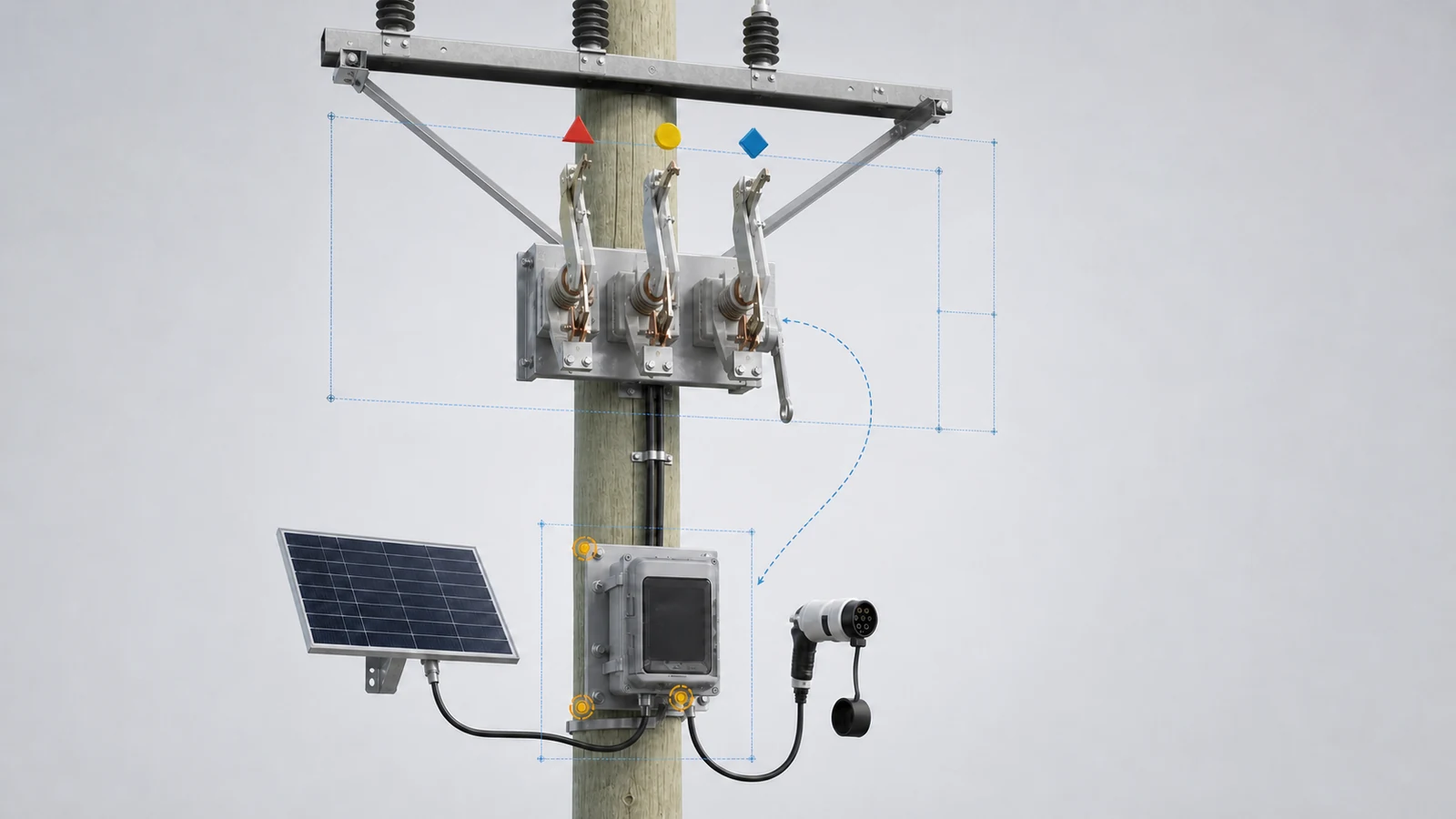
Keep the package on hold when its identity, duty, phase arrangement, mounting, access, or cable route relies on an unstated assumption.
An accessory label stating a charging voltage does not define terminal compatibility. Require the source type, nominal and allowable range, frequency, grounding arrangement, protective device, connector, cable, and approved measurement point.
A calibrated multimeter may confirm the specified quantity at that point under the authorized plan. Its calibration record belongs with the result. The measurement cannot replace the manufacturer’s allowable input range.
Build a load schedule for every item on the same source. Depending on the selected package, loads may include the ICC terminal, receiver, gateway, actuator, heater, and charging equipment. Identify continuous, intermittent, peak, and inrush duties where applicable.
Stored-energy evidence should cover battery technology, declared capacity basis, charger characteristics, alarms, environmental derating, and degraded behavior. A solar option also needs the selected panel, regulator, cable, mounting, and energy-balance basis. Do not infer autonomy from the presence of a battery or panel.
Assign voltage-drop, surge-protection, grounding, and environmental responsibilities. Define the insulation test boundary before any test. Connected electronics must remain outside that boundary unless the selected OEM manual explicitly permits the method.
The approved commissioning plan controls instruments, methods, isolation, test points, and acceptance sources. This article provides no universal voltage tolerance, battery capacity, autonomy, insulation value, or work sequence.
RS485 identifies an electrical physical interface. It does not define the application protocol, serial settings, device role, address, register map, command behavior, status meanings, time basis, access, or credentials.
The physical-layer return should cover cable, topology, termination, isolation, grounding or shield boundary, connector, and project length limits. The protocol return should state profile, baud rate, data bits, parity, stop bits, device address, and register or point map.
Map every command, status, feedback, alarm, and quality state to the project point list. Declare remote and local meanings, feedback normal states, invalid or stale behavior, and any command permissive. Do not infer a successful operation from a changing software point.
Assign device ID, password custody, user roles, configuration authority, and credential handover. Include required software, licenses, engineering cable, firmware basis, backup file, and restoration method under the project’s cybersecurity policy.
The feeder automation controller RFQ owns controller hardware and interface procurement. SG-07 verifies the selected site package, controlled configuration, mapping, and handover. It does not redesign the controller.
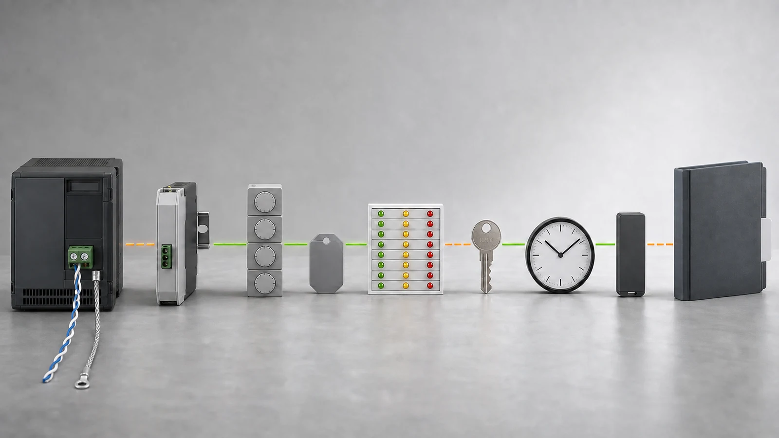
Communication remains on hold when one physical connection exists but the functional mapping or as-left configuration is incomplete.
The approved project commissioning plan and OEM manual define the required records. Organize them as one revision-controlled pack instead of separate email attachments.
| Pack item | Required evidence before release |
|---|---|
| Site and duty basis | Approved SLD, pole overlay, phase layout, no-load boundary, and operating authority |
| Package identity | Selected OEM manual, option list, packing list, model and revision reconciliation |
| Mechanical interfaces | Crossarm, bracket, clamps, terminal position, cable route, access, and photographs |
| Power package | Supply and load schedule, allowable range, charger, battery, solar, protection, and degraded behavior |
| Wiring and communication | Phase map, cable and terminal drawings, point list, protocol, settings, address, and status semantics |
| Inspection and test boundary | De-energized inspection, approved method references, instruments, calibration, exclusions, and acceptance source |
| Deviations | Owner, disposition, corrective action, retest or reinspection evidence, and closure status |
| Configuration handover | Device ID, credentials, software, firmware, backup, restoration record, and access roles |
| As-left release | Drawings, photographs, test record, deviation register, configuration files, and signed release note |
A test record should identify the approved method, instrument status, result, acceptance source, and applicable revision. A corrective action does not close a deviation until the required retest or reinspection evidence is attached.
This guide does not replace the safe-work procedure, switching order, project test plan, OEM manual, or authorized acceptance method. Those controlled documents govern actual site activity.
Representative diagnostic example, entirely synthetic, illustrative, and non-universal. This is not a XIYA POWER customer, supplier, factory, installation, test, commissioning, maintenance, failure, outage, or field case. No successful communication, operation, acceptance, or result is claimed.
The review uses one selected 12 kV DGDW1 body with an ICC terminal package. The site package requests a handheld controller, motor cable, and solar charging at one remote pole.
The return includes an AC 220 V charging cable. It lacks controlled solar-panel, charger, battery-capacity, autonomy, and low-voltage behavior data. The site source is 230 V AC nominal.
A synthetic calibrated-multimeter record measured 247 V AC and 50 Hz at the proposed charging point. The terminal’s allowed input range is absent, so the measurement cannot close compatibility.
The project requests RS485 Modbus RTU at 19,200 bit/s, 8 data bits, even parity, and 1 stop bit. The return says RS485 only. It lacks protocol, register map, isolation, termination, address, and configuration evidence.
The project assigns device ID 17, but password custody and credential handover are unassigned. Its cable schedule uses A/B/C, while site markers use R/Y/B without an approved cross-reference.
The overlay places the ICC terminal 1.5 m below the crossarm and shows a 4.8 m route. The returned motor cable is 4.0 m. Stroke-feedback and indicator normal states are undeclared.
Synthetic illustrative review table:
| Decision | Observed return | Release state | Required evidence |
|---|---|---|---|
| Package, duty, and phase map | Package reconciliation and A/B/C-to-R/Y/B mapping are incomplete | Hold | Controlled packing list, signed no-load boundary, and approved phase map |
| Power, charging, and degraded state | Site measurement exists, but allowable range, solar, charger, battery, and low-voltage behavior are open | Hold | OEM range, complete charging return, load and autonomy basis, and degraded-state statement |
| Communication and access | RS485 is named, while protocol, map, address, settings, and credentials remain open | Hold | Confirmed profile, serial settings, point list, device address, backup, and credential handover |
| Mounting, cable, status, and records | Route exceeds returned cable length; feedback states and as-left records are absent | Hold | Toleranced overlay, compliant cable solution, declared states, test boundary, and signed as-left pack |
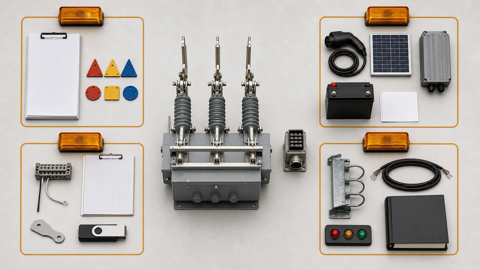
The review does not accept or reject the package. It does not claim installation, energization, communication, testing, commissioning, reliability, or operation.
Confirm the selected body and terminal package, no-load duty, site overlay, mounting and cable route, power and charging basis, phase map, status semantics, communication profile, credentials, and required records.
No. The OEM must declare the terminal’s allowable input range and interface. Compare that evidence with the approved site source, protection, connector, test point, and referenced measurement.
No. Also define cable and termination, protocol, serial settings, address, point map, command and status meanings, quality states, time basis, access roles, credentials, and configuration handover.
Map every motor plug to the approved site phase convention. Cross-reference actuator commands, stroke feedback, remote and local states, charging indication, link state, and normal point meanings.
Include the approved site and duty basis, package reconciliation, drawings, power evidence, phase and point maps, inspection and test records, deviations, configuration backups, credentials handover, photographs, and release note.
Hold release whenever a required identity, duty, power, mounting, phase, status, communication, credential, test-boundary, deviation, or as-left record remains missing, incompatible, uncontrolled, or unsigned.