Quotation form
Send an inquiry
Start with the basics. Our team can follow up for missing drawings, standards or packing details.
Submitted details are used only for quotation, technical review and project communication.

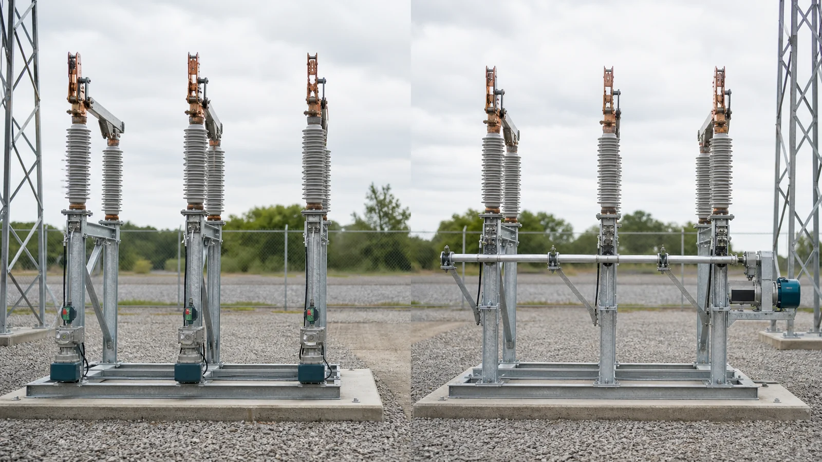
The single pole vs gang operated disconnect switch decision concerns how one command reaches three phase poles and how each pole’s final state is proved. Independent-pole arrangements give each phase its own drive path. Gang-operated arrangements use one mechanism plus a cross-phase shaft, rod, or linkage.
Choose from structures, spacing, linkage route, command authority, per-pole position evidence, access, maintenance, and configuration-specific documentation. Neither arrangement changes the switch’s approved electrical duty or by itself authorizes single-phase operation under load.
The Distribution Switching Equipment pillar separates switch duty from the physical operating package. Use the earlier air-break and disconnect duty guide to establish what the exact device may switch before comparing phase operation.
| Decision layer | Required input | Independent-pole implication | Gang implication | Release evidence | Hold condition |
|---|---|---|---|---|---|
| Feeder/substation role | Approved duty and line/bay position | Separate drive at each pole | One normal drive for three poles | Duty and one-line basis | Duty remains unresolved |
| Phase layout | Coordinates, spacing and structures | Three mechanism/operating locations | Cross-phase linkage route and supports | Controlled plan/elevation | Coordinates are assumed |
| Mechanism path | Geometry and output requirements | Each phase path matched separately | One input transmitted across couplings | Configuration drawings | Generic mechanism offered |
| Command/authority | Manual/remote philosophy | Multiple operating or control paths | One normal command path | Authority matrix | State ownership is missing |
| Position/status | Local/remote/interlock needs | Evidence allocated per phase | Mechanism state reconciled with each phase | Per-pole state schedule | One indication stands for all poles |
| Access/maintenance | Safe isolation and work plan | Separate adjustments after full safe isolation | Common shaft affects all phase adjustments | Access/instruction package | Removal envelope is unchecked |
| Evidence | Applicable drawings, tests and records | Three-drive scope where used | Mechanism, shaft and support scope | Applicability statement | Evidence covers another arrangement |
Single-pole describes a separate operating point or drive per phase; it does not necessarily mean a single-phase system. Gang-operated describes mechanically linked three-pole operation; it does not prove equal travel or complete position at every pole.
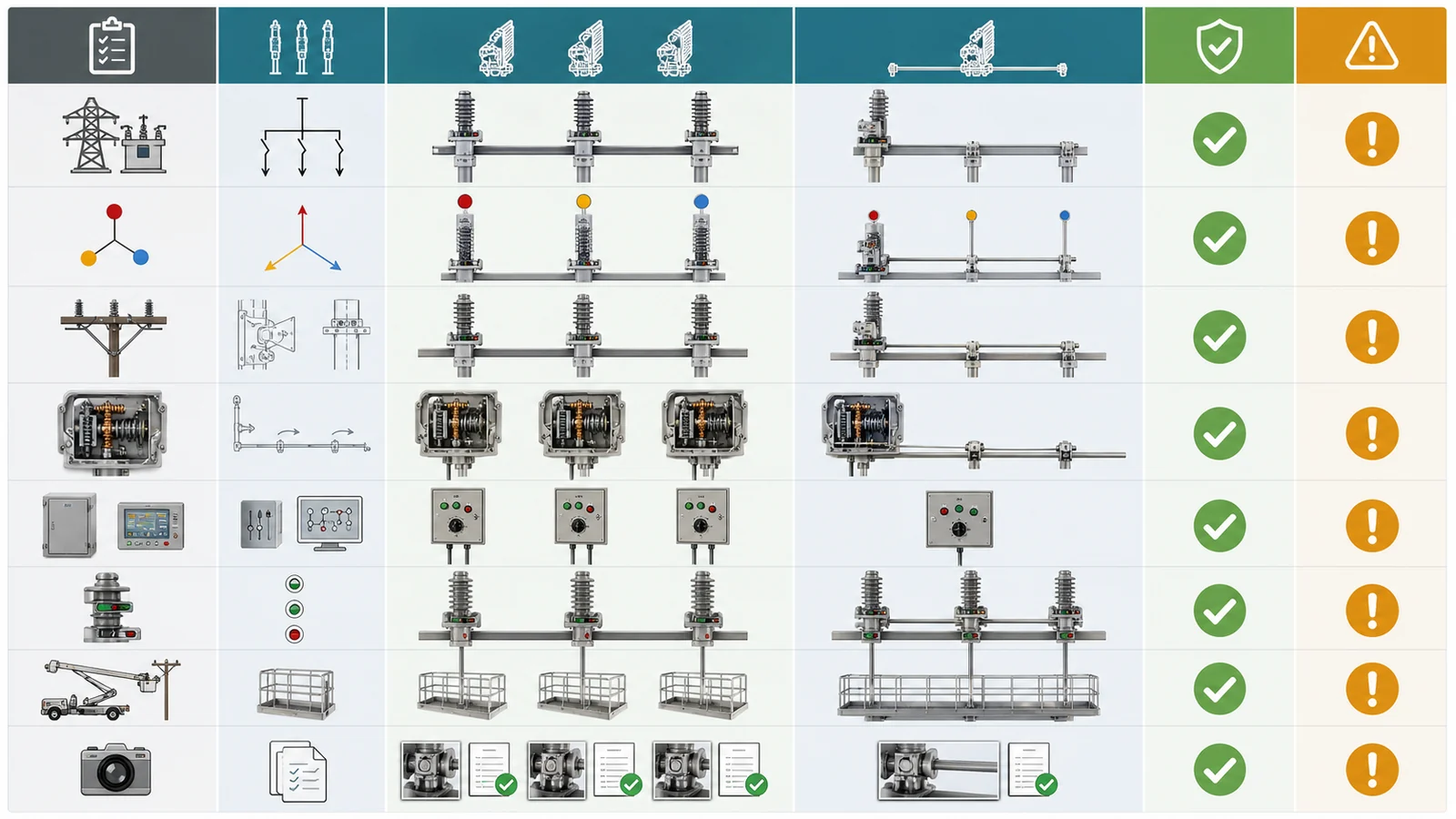
Both arrangements can appear within the Outdoor Disconnect Switches family. Manual versus motorized drive is a separate choice: independent poles may use separate handles or motors, while a gang arrangement may use one manual or motor mechanism.
| Comparison point | Independent-pole arrangement | Three-pole gang arrangement |
|---|---|---|
| Normal command | Separate phase drives, possibly coordinated by one command | One mechanism command |
| Mechanical path | No common cross-phase drive | Shaft/rod/linkage connects all poles |
| Structure | Mechanism support at each operated pole | Mechanism plus intermediate shaft supports |
| Phase state | Separate state source at each pole | Mechanism state plus reconciliation at each pole |
| Controls/status | Multiple feeds/commands/status points when motorized | One mechanism package; per-pole evidence as required |
| Adjustment | Each phase path adjusted separately | Couplings and accumulated lost motion affect the chain |
| Main hold risk | Authority, multiple interfaces and phase-discrepancy ownership | Shaft alignment, support, lost motion and far-pole evidence |
A gang arrangement can reduce normal command interfaces, but its common linkage adds support and alignment work. Independent drives remove the common shaft but multiply drive, energy, control, indication and maintenance interfaces. Compare actual scope rather than assuming one is simpler, cheaper, faster, safer or more reliable.
On an overhead feeder, decisive inputs often include pole or crossarm arrangement, operating height, whether the phases share one structure, ground-level versus hook-stick access, and how the required open state is confirmed before maintenance. A gang drive can consolidate normal operation at one location, but its rods, bearings and crossarm interfaces must suit the complete structure. Separate pole units can fit dispersed phase positions, but the operator or control system then has three states to complete and verify.
In an outdoor substation, fixed phase coordinates, separate foundations, bus geometry, cable trenches, equipment frames and operating aisles make the cross-bay route important. One gang mechanism may reduce normal command wiring while adding long-shaft supports and adjustment points. Three independent motor drives may avoid that route while adding three control-power drops, local mechanisms, manual interfaces and status channels. These are project tendencies, not feeder-versus-substation rules.
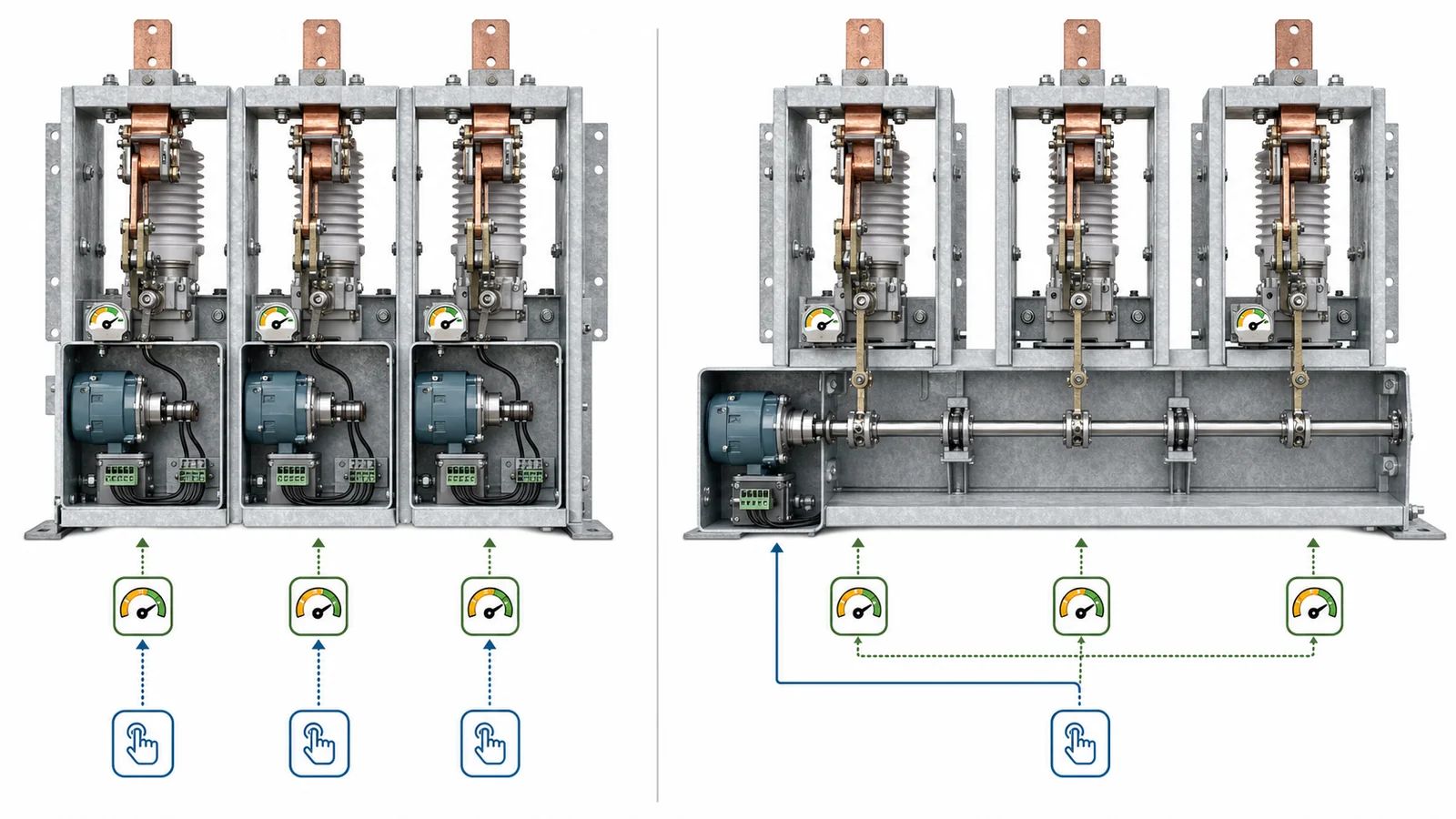
Approved break geometry is an input. The center-, double-, and vertical-break comparison owns the blade path and bay envelope; DSE-09 asks how the selected geometry is operated across the phases.
For both offers, normalize phase coordinates, mounting-face elevations, base patterns, mechanism side, operating aisle, structures, bus/terminal constraints, and open/closed working envelopes. Then compare the mechanical chain.
For a gang offer, require the cross-phase shaft or rod route, intermediate bearings/supports, couplings, alignment/adjustment points, allowable lost motion, output direction, and evidence at the nearest and farthest poles. A mechanism reaching its stop does not demonstrate that the far pole achieved the same required state.
For an independent offer, require each mechanism mounting, output linkage, local/manual access, supply/control route where motorized, and the way coordinated operation is commanded and confirmed. Sending one command to three drives does not prove all three completed travel.
Maintenance comparison begins only after the project safe-isolation boundary is established for the equipment. Independent paths can allow phase-specific mechanical adjustment without disturbing a common shaft; a gang path may require coupling disconnection and full realignment after work. That does not imply adjacent phases may remain energized. Require lifting/removal envelopes, access drawings, adjustment instructions, and configuration-specific open/closed operation records rather than a generic maintenance claim.
The disconnect switch operating mechanism guide owns manual/motor selection, power, interlock interfaces and auxiliary contacts. Here those functions are allocated across three phase poles.
The public page for IEC 62271-102:2018 covers indoor and outdoor AC disconnectors and earthing switches above 1,000 V and up to 60 Hz. Its public change summary includes isolating-distance, position indication/signalling, interlocking and operating-force topics. It does not select phase-operation architecture, status devices, discrepancy logic, timing or tolerances for this project.
| State/evidence layer | Gang arrangement | Independent-pole arrangement | Release question |
|---|---|---|---|
| Command accepted | One mechanism command | Coordinated or separately authorized commands | Who owns command authority? |
| Drive travel | One mechanism travel state | One travel state per drive | What does each device actually sense? |
| Phase A/B/C position | Evidence at each primary pole as required by use | Evidence from each pole/drive relationship | Is every phase state traceable? |
| Local indication | Mechanism indication plus declared pole relationship | Per-pole indication/operating point | Can an operator verify required state? |
| Remote/interlock status | Composite and/or per-pole points by project | Per-pole points and any composite state | Which state releases each interface? |
| Discrepancy | Mechanism versus one or more pole states | Commanded state versus one or more drives/poles | Who detects, alarms and owns response? |
Per-pole evidence may be a mechanically referenced indicator, contact, sensor, inspection mark, or another approved method. Electrical contacts are required only where the remote status, alarm or interlock design needs them. Do not equate a gang mechanism indicator with all three primary poles, or a simultaneous independent-drive command with successful three-pole completion.
Define the discrepancy boundary and response owner without inventing universal logic or timing. Detailed control schematics and operating procedures remain project-specific.
Before release, trace every status used by operations or an interlock back to the physical point it represents. Record whether it senses mechanism output, a phase linkage or the primary moving contact; whether open, closed and intermediate states are distinguishable; whether the state is available locally, remotely or both; and what happens when the three pole indications disagree. If a composite all open or all closed signal is required, document how its contributing phase states are formed and tested. A composite indication must not conceal which pole failed to reach the commanded state.
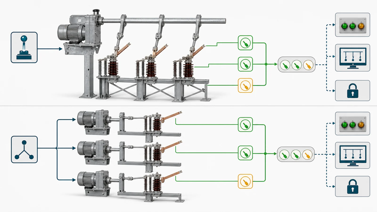
RFQ checklist and approval data pack — required project inputs:
Per-offer return package:
Keep manufacturer data, the project specification, and the short-circuit study as distinct sources. The study supports the electrical and withstand basis; phase-operation fit still depends on geometry, structures, mechanism interfaces and applicable evidence.
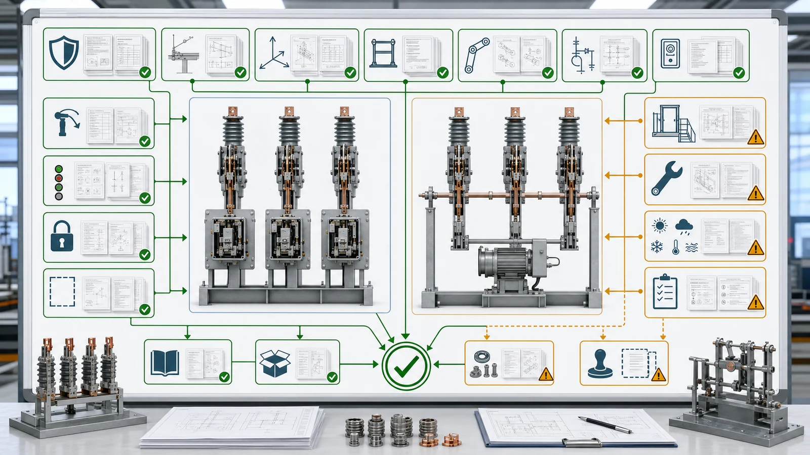
Representative engineering review, not a XIYA POWER customer, utility, factory, field, FAT, commissioning, maintenance, outage, or service case. All values are illustrative and non-universal.
Consider an illustrative 72.5 kV outdoor line-bay retrofit. Three phase bases are fixed on existing structures at approximately 2.5 m centers. A gang offer uses one motor mechanism and an approximately 6 m cross-bay shaft/linkage. An independent offer uses three motor mechanisms on the same station control source with a coordinated command and per-pole status.
The gang offer must close shaft-support locations, compatibility with existing mounting faces, coupling/alignment and lost-motion limits, manual access, adjustment, and primary position evidence at all three poles. The independent offer must close three power/control routes, terminal capacity, authority, manual method, per-pole position/status, and ownership of a condition in which one phase does not reach the commanded state.
Both offers must return the same structure, position-evidence, maintenance, applicability and deviation records. Selection remains held: the gang mechanism indicator does not close far-pole evidence, and coordinated dispatch to three motors does not close successful three-pole operation. No winner can be chosen until both architectures are normalized on the same project basis.
Installation and maintenance scope must also be normalized. The gang offer should identify shaft shipment sections, field couplings, support brackets, alignment checks and the as-set record. The independent offer should identify three mechanism enclosures, terminal groups, local/manual access points, cable entries and the method for confirming a coordinated final state. Describing one option as fewer devices or the other as fewer mechanical parts is not a technical decision unless the associated interfaces and evidence are included.
An independent-pole arrangement gives each phase a separate operating path or mechanism. A gang-operated arrangement uses one mechanism and a common shaft, rod or linkage to drive three phase poles. The distinction concerns motion transmission, not electrical duty.
No permission follows from the architecture label. Any current-switching action must remain within the exact device’s approved duty and project operating rules. Independent-pole construction alone does not authorize loaded single-phase operation.
Yes. Each pole can have a motor drive and receive a coordinated command, subject to complete power, control, authority, position-status and discrepancy engineering. Independent-pole and motorized are separate specification attributes.
Not by itself. It indicates the state sensed at the mechanism. Shaft supports, couplings, adjustment and lost motion can affect the relationship to each primary pole, so the approved design must provide suitable per-pole evidence.
Neither universally. Independent paths avoid common-shaft realignment but create multiple mechanisms and interfaces. Gang operation uses one mechanism but adds cross-phase supports, couplings and coordinated adjustment. Compare safe access, instructions, spares and configuration records.
Require controlled phase coordinates, switch/mechanism arrangements, base/support loads, linkage/support details, open/closed per-pole views, power/control/terminal documents, position/status allocation, interlock/discrepancy narrative, instructions, applicable tests and deviations.



